D400-08-00 REV#-002 1 I56-1007-000
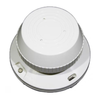
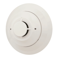
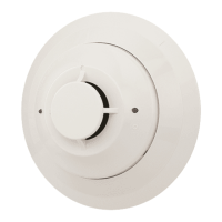
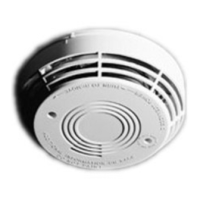
1412A and 1424A Direct Wire
Ionization Smoke Detectors
INSTALLATION AND MAINTENANCE INSTRUCTIONS
Before Installing
Please thoroughly read the System Sensor manual I56-
407-XX, Guide for Proper Use of System Smoke Detec-
tors, which provides detailed information on detector
spacing, placement, zoning, wiring, and special appli-
cations. Copies of this manual are available at no charge
from System Sensor. Please also refer to CAN/ULC-S524,
Standard for the Installation of Fire Alarm Systems and
CEC Part 1, Sec. 32..
General Description
System Sensor 1412A and 1424A dual-chamber ionization
smoke detectors utilize state-of-the-art, unipolar sensing
chambers. These detectors are designed to provide open
area protection, and to be used with ULC-listed 4-wire
control panels. The 1412A for 12 volt panels operates
at 12VDC, and the 1424A for 24 volt panels operates at
24VDC. The detectors’ operation and sensitivity can be
tested in place. These detectors are latching type system
detectors. When latched in alarm, the detectors must be
reset by a momentary power interruption.
An LED on the detector provides a local indication of the
Specifications
Diameter: 5.5 inches (14 cm)
Height: 3.12 inches (8.0 cm)
Weight: 0.7 lb (310 gm)
Operating Temperature: 0° to +49°C (32° to 120°F)
Operating Humidity: 10% to 93% Relative Humidity Non-condensing
Locking Alarm: Reset by momentary power interruption.
Relay Contact Ratings
Resistive or Inductive (60% power factor) load
Form A: 2.0A @ 30VAC/DC
Form C: 2.0A @ 30VAC/DC
Electrical Ratings: 1412A 1424A
System Voltage: 12 24 DC (4V Maximum Ripple)
Supply Voltages: 11.3 20 VDC Minimum
17.3 29 VDC Maximum
Reset Voltages: .73 .8 VDC Minimum
Standby Current: 100 100 µA Maximum
Alarm Currents: 35.2 21.3 mA Minimum
77.0 40.6 mA Maximum
The alarm and auxiliary relay operate within the specied voltage ratings.
Reset Time: 0.3 0.3 Seconds
Start-up Time: 30 30 Seconds
detector’s status. If power is applied to the detector, and
the detector is functioning properly in standby, the status
LED will blink every 10 seconds. In alarm, the LED will be
latched on continuously until the detector is reset.
Each detector contains one Form A (SPST-NO) contact
for connection to the alarm-initiating circuit, and one Form
C (SPDT-NO/NC) set of auxiliary contacts. Supervision of
detector power is accomplished by installing a Power Su-
pervisory End-of-Line Relay Module (A77-716) at the end
of the detector power loop. When power is applied to and
through the detectors, the EOL Power Supervisory Module
is energized. Its relay contacts close and provide a closed
series circuit in the control panel’s alarm-initiating loop. A
power failure or a break in the detector power loop de-
energizes the EOL Module. The relay contacts open and
trigger a trouble signal at the control panel.
6581 Kitimat Rd., Unit #6, Mississauga, Ontario, L5N 3T5
1-800-SENSOR2, FAX: 905-812-0771
WWW.SYSTEMSENSOR.CA