D400-06-00 1 I56-286-03
2412, 2412TH, 2424, and 2424TH
Direct Wire Photoelectronic
Smoke Detectors
INSTALLATION AND MAINTENANCE INSTRUCTIONS
A Division of Pittway
3825 Ohio Avenue, St. Charles, Illinois 60174
1-800-SENSOR2, FAX: 630-377-6495
Before Installing
Please thoroughly read the System Sensor manual I56-407-
XX, Guide for Proper Use of System Smoke Detectors, which
provides detailed information on detector spacing, place-
ment, zoning, wiring, and special applications. Copies of
this manual are available at no charge from System Sensor.
(For installation in Canada, refer to CAN/ULC-S524, Stan-
dard for the Installation of Fire Alarm Systems and CEC
Part 1, Sec. 32.)
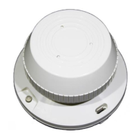
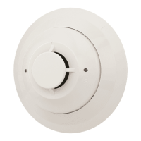
General Description
System Sensor 2412 and 2424 photoelectronic smoke detec-
tors utilize state-of-the-art, optical sensing chambers. These
detectors are designed to provide open area protection, and to
be used with compatible UL-listed 4-wire control panels only.
The 2412 applies to 12 volt panels and operates at 12VDC,
and the 2424 applies to 24 volt panels and operates at
24VDC. Operation and sensitivity can be tested in place.
Models 2412TH and 2424TH have the same specifications as
models 2412 and 2424, but in addition feature a built-in fixed
Specifications
Diameter: 5.5 inches (14 cm)
Height: 3.19 inches (81 mm); Add 0.5 inches (1.3 cm) for thermal units
Weight: 0.7 lb (310 g)
Operating Temperature Range: 2412 and 2424 — 0° to +49°C (32° to 120°F)
2412TH and 2424TH — 0° to +38°C (32° to 100°F)
Operating Humidity Range: 10% to 93% Relative Humidity
Maximum Air Velocity: 3000 Ft./Min. (15 M/S)
Latching Alarm: Reset by momentary power interruption.
Electrical Ratings 2412 2424
System Voltage: 12 24 DC (4V Maximum Ripple)
Supply Voltage: 11.3 20 VDC Minimum
17 29 VDC Maximum
Reset Voltage: .73 .8 VDC Minimum
Standby Current: 120 120
µ
A Maximum
Alarm Currents: 35 21.3 mA Minimum
77 40.6 mA Maximum
The alarm and auxiliary relay operate within the specified voltage ratings.
Start-up Time: 34 34 S Maximum
EOL Relay: A77-716 A77-716
Reset Time: 0.3 0.3
Relay Contacts – resistive or inductive (60% power factor) load:
Form A: 2.0A @ 30VAC/DC
Form C:* 0.6A @ 110VDC; 2.0A @ 30VDC
1.0A @ 125VAC; 2.0A @ 30VAC
(*For Canadian installations, relay contact rating is 2.0A @ 30VAC/DC)
temperature (135°F) thermal detection unit.
An LED on each detector lights to provide a local alarm indi-
cation. It flashes every ten seconds indicating that power is
applied to the detector. The LED lights continuously in alarm.
These detectors also have the latching alarm feature that re-
sets only by a momentary power interruption.
Each detector contains one set of Form A contacts for connec-
tion to the alarm-initiating circuit, and one set of Form C aux-
iliary contacts. Supervision of detector power is
accomplished by installing a Power Supervisory End-of-Line
Relay Module (A77-716 Series) at the end of the detector
power loop. When power is applied to and through the detec-
tors, the EOL Power Supervisory Module is energized. Its re-
lay contacts close and provide a closed series circuit in the
control panel’s alarm-initiating loop. A power failure or a
break in the detector power loop de-energizes the EOL Mod-
ule. The relay contacts open and trigger a trouble signal at the
control panel.
Technical Manuals Online! - http://www.tech-man.com