15
19
14
3
20
1
3
2
Alarm Signal
Aux. Power +
Sup. N. O.
Sup. COM
Aux. Power —
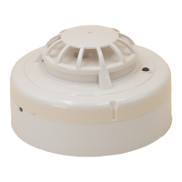
NOTE: Wiring diagram shown is for DH100ACDCLWP 4-wire duct
smoke detector system equipped without a control panel.
Alarm
(Red LED)
Power
(Green LED)
Common
4-Wire Wiring to APA451
APA451DH100ACDC
Figure 8. Wiring diagram for DH100ACDCLP
to APA451:
A78-2352-11
Figure 7. System wiring diagram for 4-wire duct smoke detectors:
Figure 9. Wiring diagram for DH100ACDCLP to
RTS451KEY and interconnect feature:
Important Interconnect Notes
• When using the interconnect feature, all in-
terconnected units must be powered with
the same, independent supply.
• Polarity must be maintained throughout the
interconnect wiring. Connect terminal 12 on
unit 1 to terminal 12 on unit 2 and so on.
Similarly, connect terminal 1 on unit 1 to ter-
minal 1 on unit 2 and so on.
Figure 10. Multiple fan shutdown (interconnect):
1
6
12
16
A
B
C
FAN
CONTROL
SYSTEM
CONTROL
POWER OR
THERMOSTAT
1
6
12
16
A
B
FAN
CONTROL
SYSTEM
CONTROL
POWER OR
THERMOSTAT
DETECTOR 1
C
DETECTOR 2
1
6
12
16
A
B
FAN
CONTROL
SYSTEM
CONTROL
POWER OR
THERMOSTAT
C
DETECTOR 3
1
12
—
+
NEXT
DETECTOR
 Loading...