D300-02-01 I56-1719-020
+
-
V- V-
2
1
3
4
5
4351E
5351E
5351TE
-30°C
70°C
105 g
102 mm
60 mm
Declaration of Performance Ref:
4351E: 0832-CPD-0061
5351E: 0832-CPD-0062
5351TE: 0832-CPD-0063
Pittway Tecnologica
S.r.l,
Via Caboto 19/3,
34147 Trieste, Italy
0832 05
B401x
57mm
Pittway Tecnologica S.r.l. Via Caboto 19/3, 34147 TRIESTE, Italy
R
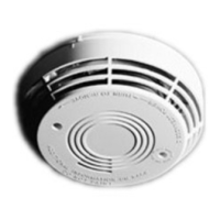
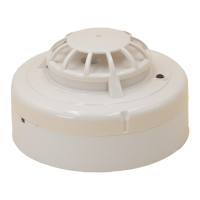
INSTALLATION AND MAINTENANCE INSTRUCTIONS
4351E 78°C FIXED TEMPERATURE
5351E 58°C plus RATE OF RISE
5351TE 58°C FIXED TEMPERATURE
GENERAL DESCRIPTION
Model 4351E, 5351E and 5351TE heat detectors use a single thermistor sensing element
combined with state of the art electronics to provide ambient temperature compensation
and fast response. The ability to plug these sensors into a variety of base options extends
panel compatibility and application exibility. These sensors are designed to provide
open area protection and are only to be used with compatible control panels.
A bicolour LED on each sensor lights red to provide a local visible alarm indication, ashes
yellow to indicate a chamber fault or drift compensation limit reached, and may also be
set to ash green to indicate correct operation of the sensor. Remote LED annunciator
capability is available as an optional accessory wired to the standard base terminals.
These sensors also have a latching alarm feature. The alarm can be reset only by a
momentary power interruption.
A dedicated tool is available from System Sensor, which may be used to access operating
data from the sensor.
*4351E ALARM
THRESHOLD IS 78°C
Figure 1: Base Terminal Wiring
NOTE: WHEN A BASE FITTED WITH A
RESISTOR (R) - BETWEEN TERMINALS
4 AND 5 - IS USED, THE WIRING SHOULD
FOLLOW THE DASHED LINE.
SHORTING SPRING
TO ACTIVATE, BREAK TAB ON PLASTIC
LEVER AT DOTTED LINE BY TWISTING
TOWARD CENTRE OF BASE
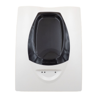
Figure 2: Tamper Resist Feature
TO REMOVE, USE A SMALL
SCREWDRIVER TO PUSH
PLASTIC IN THE DIRECTION
OF THE ARROW, WHILST
ROTATING THE SENSOR
ANTI-CLOCKWISE
A SCHOTTKY DIODE
CONNECTED BETWEEN
TERMINALS 2 AND 3 DOES
NOT AFFECT BASE WIRING.
PLASTIC LEVER
SPECIFICATIONS
Supply voltage 8 - 30VDC
Air velocity 20m/s (4000 ft/min)
Humidity 5 - 95%RH (non-condensing)
Quiescent current 60µA Typical (4351E 65μA)
Maximum alarm current 80mA (Limited by panel or base resistance)
Latching alarm Reset by momentary power interruption.
The 5351E has been independently tested and certied to EN54-5 Class A1R.
The 5351TE has been independantly tested and certied to EN54-5 Class A2S.
The 4351E has been independently tested and certied to EN54-5 Class BS.
Note: Do not install in locations where the normal ambient temperature range extends
beyond 0°C to 50°C for extended periods.
BASE MOUNTING AND WIRING INSTRUCTIONS
Verify that the sensor base supplied is compatible with the system control panel.
400 series bases may be mounted to standard electrical junction boxes with 50-60 mm
centre xings.
See gure 1 for terminal connections on standard bases. If relay bases are to be used,
please refer to the relevant base instructions.
Notes:
1. Series 300 sensors are polarity conscious, and must be wired as indicated.
2. Do not loop wire under terminals: break the wire run to ensure supervision of
connections.
3. All wiring must conform to applicable local and national codes and regulations.
Each 400 series base is tted with a shorting spring, which may be used to connect across
terminals 2 and 3 to permit loop wiring to be checked before installation of sensor heads.
This spring automatically disengages when the sensor is tted into the base.
WARNING
Remove power from sensor monitoring circuits before installing sensors.
SENSOR INSTALLATION
1. Insert the sensor into the base and rotate it clockwise until it locks into place.
2. After all sensors have been installed, apply power to the sensor monitoring circuits.
3. Test the sensor as described under TESTING.
4. Reset the sensor at the system control panel.
Tamper-resistance
The sensor bases include a feature that, when activated, prevents removal of the sensor
without the use of a tool. See gure 2 for details.
CAUTION
Dust covers are tted to the sensors to help protect units during shipment and
when rst installed. They are not intended to provide complete protection
against contamination; therefore sensors should be removed before beginning
construction, major re-decoration or other dust producing activity. Dust covers
must be removed before the system can be made operational.
TESTING
Sensors must be tested after installation and following periodic maintenance. Disable the
zone or system undergoing maintenance to prevent unwanted alarms. Test the sensor
as follows:
Direct Heat method
1. Use either a specialised tool such as supplied by No Climb Products Limited, or a
hairdryer of 1000 to 1500 Watts.
2. Direct the heat towards the sensor thermistor from it’s side. Hold the heat source
about 15cm away from the detector to prevent damage during the test.
3. The red LED on the detector should latch into alarm within 40 seconds, and the
control panel should activate into alarm.
Laser test tool method (model no. S300RTU)
Note: this method does not carry out a complete functional test of the sensor.
1. Align the ashing red spot produced by the laser beam with the LED on the sensor.
2. The red LED on the sensor should latch into alarm within a few seconds, and the
control panel should activate into alarm.
CAUTION
The S300RTU test tool is a Class II laser product. Do not direct the beam towards
a person’s face or eyes
After completion of all tests notify the proper authorities that the re system is operational.
MAINTENANCE
Before cleaning, disable the system to prevent unwanted alarms.
1. Remove the sensor to be cleaned from the system.
2. Use a vacuum cleaner and/or clean, compressed air to remove dust and debris from
the thermistor and sensor cover.
3. Replace the sensor into the base
4. When all the sensors have been cleaned, restore power to the circuit and test the
sensor as described in TESTING above.
WARNING - LIMITATIONS OF THERMAL SENSORS
Fire sensors must be used in conjunction with compatible equipment.
Heat sensors are designed to protect property, not life. They do not provide early
warning of re and cannot detect smoke, gas, combustion particles or ame.
Heat sensors do not always detect res because the re may be a slow smouldering,
low-heat type (producing smoke) or because they may not be near where the re occurs,
or because the heat of the re may bypass them. Consideration must be made of the
environment when selecting heat sensors.
Fire sensors cannot last forever. Fire sensors contain electronic parts. Even though
sensors are made to last over 10 years, any of these parts could fail at any time.
Therefore, test your re detection system at least semi-annually. Taking care of the re
detection system you have installed will signicantly reduce your product liability risks.
ENGLISH