Do you have a question about the System Sensor D4P120 and is the answer not in the manual?
Details the components included in the 11K76 and 11K80 smoke detector kits for various applications.
Provides essential safety warnings and explains how smoke detectors function with different unit types.
Covers initial safety, sensor/power board installation, and component placement guidance.
Details the selection, orientation, and use of sampling tubes for air stream detection.
Illustrates wiring for KC, KG, KH units and identifies key components and connectors.
Step-by-step guide for mounting the power board and securing its wiring harness for KC/KG/KH units.
Instructions for mounting the panel holder, hinged panel assembly, and securing harnesses.
Wiring diagram for KC, KG, KH units with a single return air smoke detector.
Wiring diagram for KC, KG, KH units with a single supply air smoke detector.
Wiring diagram for KC, KG, KH units with both return and supply air smoke detectors.
Steps for installing power board, hinged panel, and securing harnesses in LC/LG units.
Guidance on using the test magnet and storing maintenance/test procedure instructions.
Wiring diagram for LC/LG units with a single return air smoke detector.
Wiring diagram for LC/LG units with a single supply air smoke detector.
Wiring diagram for LC/LG units with both return and supply air smoke detectors.
The D4P120 & D4S Smoke Detector Kits, identified by part numbers 11K76, 11K80, 603408-09, and 603408-10, are designed for use with KC, KG, KH, LC, and LG092-152 units. These kits provide essential smoke detection capabilities for HVAC systems, enhancing safety by signaling the presence of smoke within the air stream.
The primary function of these smoke detector kits is to detect smoke in either the supply air, return air, or both, within an HVAC system. Upon detecting smoke, the detector sends a signal to the unit controller, which then initiates a pre-programmed response, typically de-energizing the unit to prevent the spread of smoke through the ventilation system.
For LC and LG Units, the smoke detector transmits a 24Vac signal to the unit controller when smoke is sensed. The unit controller's default mode is to de-energize the unit in response to this signal.
For KC, KG, and KH Units, the smoke detector interrupts the 24Vac signal to the unit control circuit when smoke is sensed, leading to the de-energization of the unit. This interruption acts as a critical safety measure, ensuring that the HVAC system ceases operation to contain potential fire hazards.
The kits are available in two main configurations:
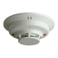
Each kit includes a smoke detector sensor, a smoke detector power board, and various mounting and wiring components necessary for installation. Sampling tubes are critical components, with a 36-inch metal sampling tube for supply air applications and an 18-inch metal sampling tube for return air applications. These tubes are designed with holes that must point toward the air stream to effectively draw air samples for detection. A plastic exhaust tube is included for return air applications to direct exhaust air away from the sensor, while it is not used in supply air applications and should be discarded.
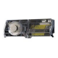
The power board is a central component, providing power and control logic for the smoke detector sensors. It is typically mounted on a hinged panel within the unit's control box, allowing for easy access for installation and maintenance. The wiring harnesses are clearly labeled to ensure correct connections between the power board, sensors, and the unit's control circuit.
The installation process involves several key steps to ensure proper functionality. The smoke detector sensor(s) and power board are installed according to the manufacturer's instructions, with specific locations designated for the power board, supply air sensor, and return air sensor within the HVAC unit.
The sampling tubes are crucial for effective smoke detection. The appropriate length of the metal sampling tube (36-inch for supply air, 18-inch for return air) must be selected and slid onto the back side of the sensor. For return air applications, the plastic exhaust tube is also attached to the back side of the sensor. Correct orientation of the sampling tube, with holes pointing toward the air stream, is vital for accurate air sampling.
Wiring connections are clearly outlined, with connectors identified by labels stamped on the wires. For KC, KG, and KH units, specific wiring routes are provided for the supply air harness and return air harness, connecting to the respective sensors and the power board. Unit wires labeled 1 and 4 are disconnected and reconnected to the kit harness wires, ensuring proper integration with the unit's control system. The power board harness is routed behind the hinged panel, and all harnesses are secured using insertion-type wire ties to maintain an organized and safe wiring environment.
For LC and LG units, the installation process is similar, involving the installation of the power board and hinged panel in the control box. If a DDC (Direct Digital Control) is factory-installed, the hinged panel may already be in place. Harness ends are secured to insertion-type wire ties, and jack/plug connections are made according to the specific application (single return air, single supply air, or both). The harness P252/P253 is factory-installed and located near the supply sensor and power board hinged panel, with plugs situated near the sensor(s) and power board for convenient connection.
The kits are designed to be flexible, supporting various configurations:
Maintenance and testing are critical to ensure the continued reliability of the smoke detector kits. Each sensor is provided with a test magnet, which is used during test procedures. The magnet is removed from its bag assembly and placed on a metal surface near the sensor to simulate smoke detection and verify the sensor's functionality.
The sensor manufacturer's instructions, which are included with each sensor, provide detailed information on maintenance and test procedures. These instructions should be placed in the literature pouch for future reference, ensuring that service personnel have easy access to the necessary guidelines for routine checks and troubleshooting.
Regular maintenance, as outlined in the manufacturer's instructions, helps to ensure that the smoke detectors remain operational and can effectively detect smoke in an emergency. This includes periodic cleaning of the sensors and sampling tubes to prevent dust and debris buildup, which could impair their performance. The modular design of the kits, with clearly labeled components and harnesses, facilitates easier replacement of parts if necessary.
The hinged panel design for the power board allows for convenient access for inspection, wiring verification, and any necessary adjustments or repairs. This accessibility reduces the time and effort required for maintenance tasks.
Important Safety Information: A warning is provided regarding sharp metallic edges within the unit, advising caution during servicing to prevent injury. Another warning emphasizes that improper installation, adjustment, alteration, service, or maintenance can lead to property damage, personal injury, or loss of life. It explicitly states that installation and service must be performed by a licensed professional installer, service agency, or the gas supplier, underscoring the importance of qualified personnel for all work related to these devices. Before performing any service or maintenance, it is crucial to turn off the electrical power to the unit at the disconnect switch to ensure safety.
| Power Source | 120 VAC |
|---|---|
| Operating Temperature | 32°F to 120°F (0°C to 49°C) |
| Type | Photoelectric |
| Battery Backup | 9 VDC |
| Sound Level | 85dB at 10 feet |
| Alarm Reset | Automatic |