SS-300-000 1 I56-2967-000R
D4120 Air Duct Smoke Detector with Extended
Air Speed Range, D4S Air Duct Smoke Detector
Sensor Component, D4P120 Air Duct Smoke
Detector Power Board Component
INSTALLATION AND MAINTENANCE INSTRUCTIONS
3825 Ohio Avenue, St. Charles, Illinois 60174
1-800-SENSOR2, FAX: 630-377-6495
www.systemsensor.com
Table of Contents Page
[1]
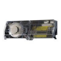
Exploded View of Duct Smoke Detector Components
.............2
[2] General Description . . . . . . . . . . . . . . . . . . . . . . . . . . . . . . . . . . . 2
[3] Limitations of Duct Smoke Detectors .......................2
[4] Contents of Duct Smoke Detector Kit .......................2
[5] Detector Installation ...................................2
[6]
Sampling Tube Installation
. . . . . . . . . . . . . . . . . . . . . . . . . . . . . . . 3
I56-2967-000R
NOTE: D4S Sensor Component and D4P120 Power Board Component to be used in conjunction with the model D4120 air duct smoke detector only.
Specifications
Operating Temperature: –4° to 158° F (–20° to 70° C)
Storage Temperature: –22° to 158° F (–30° to 70° C)
Humidity: 0% to 95% R.H. non-condensing
Air Velocity: 100 to 4000 ft./min. (0.5 to 20.3 m/sec.)
D4120 Footprint Dimensions: Rectangular - 14.38˝ L x 5˝ W x 2.5˝ D (37cm L x 12.7cm W x 6.36cm D)
Square - 7.75” L x 9” W x 2.5” D (19.7cm L x 22.9cm W x 6.35cm D)
D4S/D4P120 Footprint Dimensions: 7.75”L x 5”W x 2.5”D (19.7cm L x 12.7cm W x 6.35cm D)
D4120 Weight: 2.5 pounds; 1.14 kg
Electrical
Power supply voltage: 20-29 VDC 24 VAC 50-60-Hz 120 VAC 50-60 Hz
Input capacitance: 270 µF max. 270 µF max. N/A
Reset Voltage: 3.0 VDC min. 2.0 VAC min. 10 VAC min.
Reset Time (with RTS451): .03 to 0.3 sec. .03 to 0.3 sec. .03 to 0.3 sec.
Reset Time (by power down): 0.6 sec. max. 0.6 sec. max. 0.6 sec. max.
Power Up Time: 35 sec. max. 35 sec. max. 35 sec. max.
Alarm response time: 15 sec. 15 sec. 15 sec.
Sensitivity Test: See detector label See detector label See detector label
Current Requirements (Using No Accessories)
Max. standby current 25 mA @ 24 VDC 55 mA RMS @ 24VAC 60Hz 20 mA RMS* @ 120 VAC 60 Hz
Max. alarm current 60 mA @ 24 VDC 130 mA RMS @ 24 VAC 60 Hz 35 mA RMS* @ 120 VAC 60 Hz
CONTACT RATINGS
Alarm initiation contacts (SPST) 2.0A @ 30 VDC (resistive)
Alarm auxiliary contatcs (DPDT) 10A @30 VDC (resistive)
10A @250 VAC (resistive)
1
/2 HP @240 VAC
1
/4 HP @120 VAC
NOTE: Alarm auxiliary contacts shall not be connected to initiating circuits of control
panels. Use the alarm initiation contact for this purpose.
Trouble Contacts (SPDT) 2.0A @ 30 VDC (resistive)
2.0A @ 125 VAC (resistive)
ACCESSORY CURRENT LOADS AT 24 VDC
DEVICE STANDBY TROUBLE ALARM
APA151/APA451 12.5mA n/a 30mA Max.
MHR/MHW 0mA n/a 29mA Max.
RA400Z 0mA n/a 10mA Max.
RTS451 0mA n/a 7.5mA Max.
RTS451KEY 12mA* n/a 7.5mA Max.
SSK451 5mA Max. 9mA Max. 30mA Max.
*NOTE: When a unit is powered at the 120VAC input, any combination
of accessories may be used such that the given accessory loads are:
60mA or less in the standby state, 110mA or less in the alarm state.
Status
Sensor LED
Designation
Power Board
LED
Designation
Description/Trouble Shooting
Sensor
Initialization
Red Blink every 5
seconds
Alternating
Green/Amber
At power up or reset at the panel the sensor will take approximately 30 seconds to initialize. Also occurs
when sensor is removed during a seven minute delay.
Standby
Green Blink every
5 seconds
Green Blink every
5 seconds
The LED on the sensor and the power board should flash approximately every 5 seconds. If the detector
and power board LEDs are not illuminated, then the detector lacks power (check wiring, panel or power
supply).
Trouble
Green Blink every
5 seconds
Amber Solid
The cover has been missing or is not secured properly for more than 7 minutes, if the cover tamper feature
is “ON” (factory default). See Figure 13. OR Sensor +, - wires are shorted. Check connections.
NOTE: If the power board Solid Amber flashes once every ten seconds the unit is not receiving valid data
from sensor. Ensure the sensor is secured in place and the sensor +, - wires are properly connected.
Maintenance
Red Blink every 5
seconds
Amber Blink The sensor is outside of its sensitivity limits and shall be cleaned or replaced. See section 9 for details.
Alarm Solid Red Solid Red The unit is in alarm.
NOTE: Each power board has a unique LED to designate each of 2 possible sensors. If only one sensor is connected, the Sensor 2 LED will not illuminate.
TABLE 1. Detector Status Indications
Table of Contents Page
[7] Field Wiring .........................................4
[8] Duct Smoke Detector Testing & Maintenance . . . . . . . . . . . . . . . . . 4
[9] Detector Cleaning .....................................5
[10] Sensor Placement . . . . . . . . . . . . . . . . . . . . . . . . . . . . . . . . . . . . 5
Wiring Diagrams . . . . . . . . . . . . . . . . . . . . . . . . . . . . . . . . . . . . . . .6-8
Warranty . . . . . . . . . . . . . . . . . . . . . . . . . . . . . . . . . . . . . . . . . . . 8