Before Installing
Read the System Sensor Guide for Proper Use of Smoke Detectors in Duct
Applications (A05-1004), which provides information on detector spac-
ing, placement, zoning, wiring, and special applications. This manual is
available online at www.systemsensor.com. NFPA Standards 72 and 90A
should also be referenced for detailed information.
NOTICE: This manual shall be left with the owner/user of this equipment.
IMPORTANT: This detector must be tested and maintained regularly fol-
lowing NFPA 72 requirements. The detector should be cleaned at least
once a year.
[2] General Description
Smoke introduced into an air duct system will be distributed throughout
the entire building. Smoke detectors designed for use in air duct systems
are used to sense the presence of smoke in the duct.
Model D4120 and D4S Duct Smoke Detectors utilize 4-wire photoelectric
technology for the detection of smoke. This detection method, when com-
bined with an efficient housing, samples air passing through the duct al-
lowing detection of a developing hazardous condition. When sufficient
smoke is sensed, an alarm signal is initiated and appropriate action can
be taken to shut off fans, blowers, change over air handling systems, etc.
These actions can facilitate the management of toxic smoke and fire gases
throughout the areas served by the duct system.
The D4120, D4P120 and D4S detectors are designed to operate on 24
VDC/VAC or 120 VAC. Alarm and supervisory relay contacts are avail-
able for control panel interface (alarm initiation), HVAC control, and
other auxiliary functions. Auxiliary relays are provided for fan shut
down. Detector interconnection provides signaling of up to 50 other
detectors in the loop for multiple fan shut down. These detectors are
not designed for 2-wire applications.
For testing, the alarm can be enabled by a test button on the power board
cover, magnet activated test switch or by the optional remote test station.
The duct smoke detector latches into alarm state when an alarm occurs.
The D4120 and D4P120 LEDs indicate the status of power, maintenance,
trouble, and local alarm conditions.
The D4120 and D4P120 can be reset by a momentary power interrup-
tion, the reset button on the front cover, the control panel, or remote reset
accessory. The D4120 and D4P120 incorporate a cover tamper feature
that provides a trouble signal after 7 minutes if the cover is removed
or improperly installed. The option for an instantaneous trouble is also
available. Proper installation of the cover removes the trouble condition.
[3] Limitations Of Duct Smoke Detectors
The National Fire Protection Association has established that DUCT DE-
TECTORS MUST NOT BE USED AS A SUBSTITUTE FOR OPEN AREA DE-
TECTOR PROTECTION as a means of providing life safety. Nor are they a
substitute for early warning in a building’s regular fire detection system.
System Sensor supports this position and strongly recommends that the
user read NFPA Standards 90A, 72, and 101. The D4120 Air Duct Smoke
Detectors are listed per UL 268A.
This device will not operate without electrical power. Fire situations may
cause an interruption of power. The system safeguards should be dis-
cussed with your local fire protection specialist.
This device will not sense smoke unless the ventilation system is operat-
ing and the cover is installed.
For this detector to function properly, it MUST be installed according to
the instructions in this manual. Furthermore, the detector MUST be oper-
ated within ALL electrical and environmental specifications listed in this
manual. Failure to comply with these requirements may prevent the detec-
tor from activating when smoke is present in the air duct.
[4] Contents Of The Duct Smoke Detector Kit
1. Sensor/power board assembly and covers
2. Three #10 sheet metal screws for mounting
3. One test magnet
4. Drilling template
5. One sampling tube end cap
6. One plastic exhaust tube
NOTE: A sampling tube must be ordered to complete the installation. It
must be the correct length for the width of the duct where it will be in-
stalled. See Table 2 on page 3 to determine the inlet tube required for
different duct widths.
[5] Detector Installation
[5.1] Verify Air Flow Direction And Velocity
Model D4120 detectors are designed to be used in air handling systems
with air velocities of 100 to 4000 feet per minute. Duct widths from 6in.
to 12ft. can be accommodated. Be sure to check engineering specifications
to ensure that the air velocity in the duct falls within these parameters. If
necessary, use a velocity meter (anemometer) to check the air velocity in
the duct.
[5.2] Determine Mounting location and Configuration
On ducts wider than 18” it is recommended that the detector be mounted
downstream of a bend, obstruction in the duct, or the supply or return
air inlet.
Exception: Installation of duct detectors can be on or within a commercial
packaged rooftop heating and air-conditioning system, fire/smoke damp-
ers and economizers. They may be mounted in either the supply and/or
return air section as determined by local code.
Once a suitable location is selected, determine if the detector is to be
mounted in a side-by-side “rectangular” configuration or a top-over-bot-
tom “square” configuration as shown in Figure 2. If mounting in the
square configuration, remove the rear attachment screw, rotate the unit at
the hinge, and replace the screw into the new attachment hole as shown in
Figure 2. Do NOT remove the hinge screw during this process. Final instal-
lation approval shall be based upon passing section 8.2.2 and 8.2.4 tests.
SS-300-000 2 I56-2967-000R
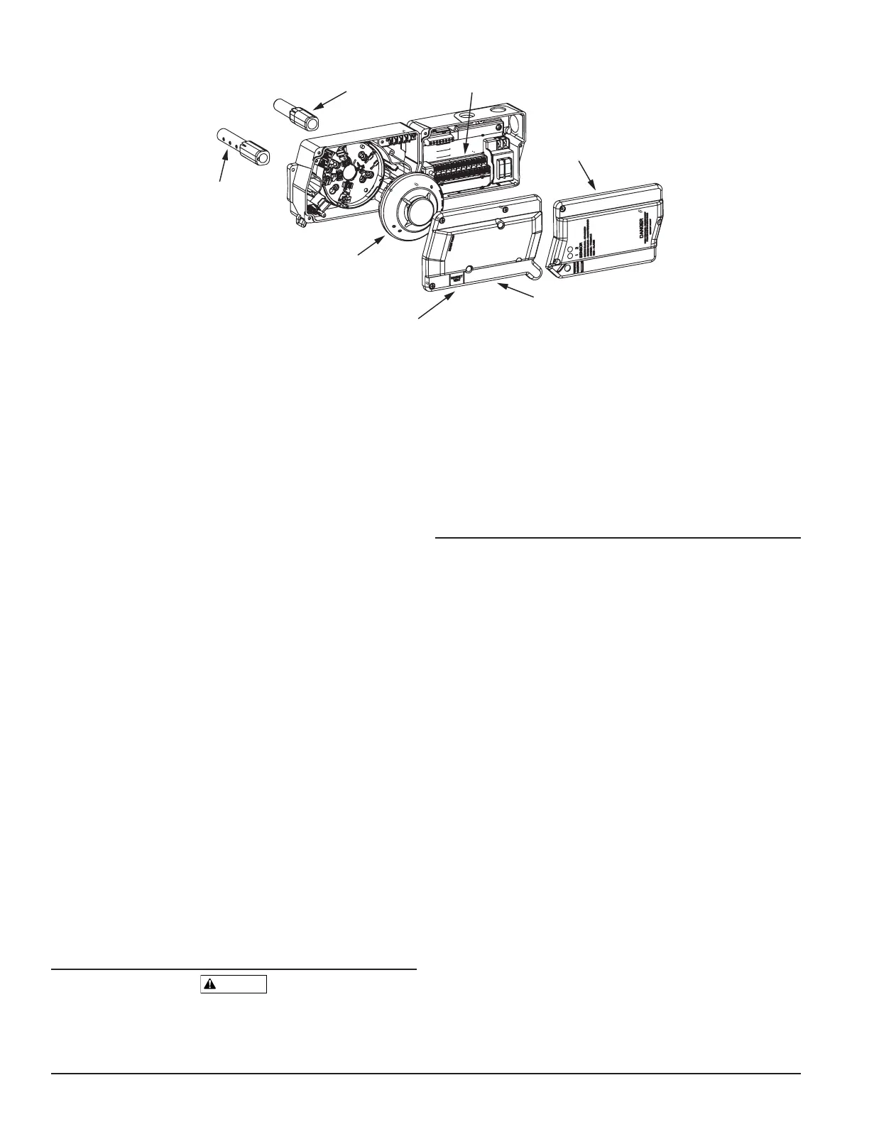
[1] Figure 1. Exploded View of Duct Smoke Detector Components:
SENSOR MODULE COVER
POWER BOARD MODULE COVER
SENSOR HEAD
METAL SAMPLING TUBE
POWER BOARD
EXHAUST TUBE
4-WIRE
MAGNET TEST LOCATION
H0549-00
 Loading...


