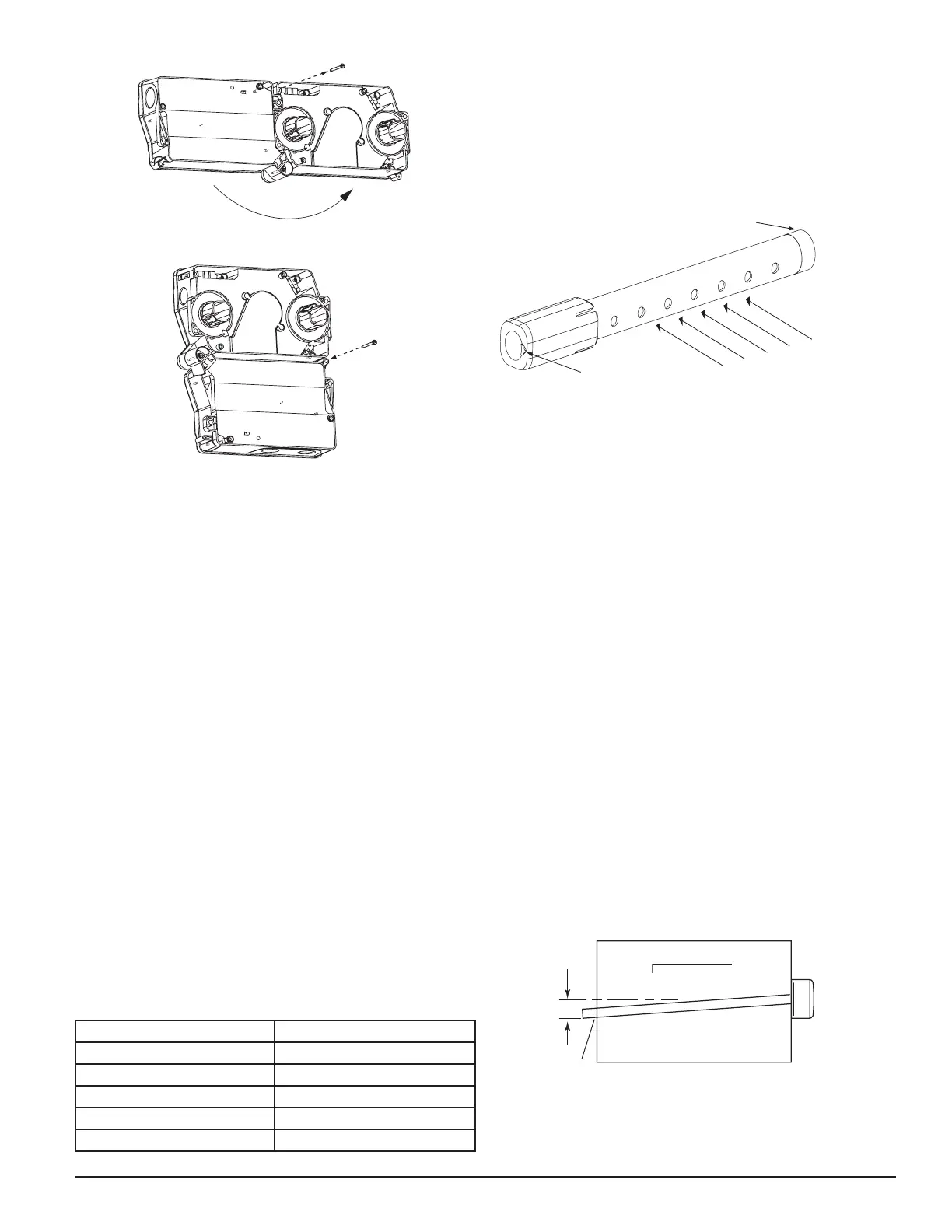
The sampling tube is always installed with the air inlet holes facing into
the air flow. To assist proper installation, the tube’s connector is marked
with an arrow. Make sure the sampling tube is mounted so that the arrow
points into the airflow as shown in Figure 3. Mounting the detector hous-
ing in a vertical orientation is acceptable provided that the air flows di-
rectly into the sampling tube holes as indicated in Figure 3. The sampling
tube and exhaust tube can be mounted in either housing connection as
long as the exhaust tube is mounted downstream from the sampling tube.
Figure 3. Air duct detector sampling tube:
SAMPLING TUBE ENDCAP
ARROW MUST FACE
INTO AIR FLOW
AIR FLOW
DIRECTION
H0551-00
NOTE: The sampling tube end cap, included with the detector, is critical to
proper operation of the duct smoke detector. The end cap is needed to cre-
ate the proper air flow to the sensor of the duct smoke detector. Once any
sampling tube length adjustments are made, plug the end of the sampling
tube with the provided end cap.
A plastic exhaust tube is included with the unit to be installed if needed.
Install into the housing connection that is downstream from the sampling
tube connection. The exhaust tube can be installed from the front or back
of the detector. A longer 1 foot exhaust tube, model ETX, is available as
an accessory in cases where the molded exhaust tube does not extend at
least 2 inches into the duct.
[6.2] Sampling Tube Installation
1. For tubes shorter than the width of the duct, slide the sampling tube,
with installed end cap, into the housing connection that meets the air-
flow first. Position the tube so the arrow points into the airflow as
shown in Figure 3. Per NFPA sampling tubes over 3 feet long should be
supported at the end opposite the duct detector. In ducts wider than 8
feet, work must be performed inside the duct to couple the other sec-
tion of the sampling tube to the section already installed using the ½”
conduit fitting supplied. Make sure that the holes on both sections of
the air inlet sampling tube are lined up and facing into the airflow.
2. For tubes longer than the width of the duct, the tube should extend out
of the opposite side of the duct. Drill a ¾” hole in the duct opposite the
hole already cut for the sampling tube. Make sure the hole is 1”-2” below
the inlet hole on the opposite side of the duct as shown in Figure 4 to
allow moisture drainage away from the detector. There should be 10 to
12 holes spaced as evenly as possible across the width of the duct. If
there are more than 2 holes in the section of the tube extending out of
the duct, select a shorter tube using Table 1. Otherwise, trim the tube to
leave approximately 1” to 2” extending outside the duct. Plug the end
with the end cap and tape closed any holes in the protruding section of
tube. Be sure to seal the duct where the tube protrudes.
Figure 4.
H0215-00
NOTE: Air currents inside the duct may cause excessive vibration, espe-
cially when the longer sampling tubes are used. In these cases, a 3” floor
flange (available at most plumbing supply stores) may be used to fasten
the sampling tube to the other side of the duct. When using the flange/
connector mounting technique, drill a 1” to 1 ¼” hole where the flange
will be used.
Figure 2:
REMOVE SCREW AND PIVOT DETECTOR AS SHOWN ABOVE.
REPLACE SCREW TO SECURE DETECTOR IN PLACE.
H0550-00
[5.3] Drill the Mounting Holes
Remove the paper backing from the mounting template supplied. Affix
the template to the duct at the desired mounting location. Make sure the
template lies flat and smooth on the duct.
[5.3.1] For rectangular side-by-side mounting configuration:
Center punch at (4) target centers: (2) “A” for sampling tubes and (2) “B”
for the rectangular configuration mounting tabs as shown on mounting
template. Drill pilot holes at target “A” centers and cut two 1.375” diam-
eter holes using a 1
3
/8” hole saw or punch. Drill .156” diameter holes us-
ing a
5
/32” drill at target “B” centers.
[5.3.2] For square top-over-bottom mounting configuration or D4S
sensor component mounting:
Center punch at (4) target centers: (2) “A” for sampling tubes and (2) “C”
for the square configuration mounting tabs as shown on mounting tem-
plate. Drill pilot holes at target “A” centers and cut two 1.375” diameter
holes using a 1
3
/8” hole saw or punch. Drill .156” diameter holes using a
5
/32” drill at target “C” centers. If desired, drill an additional .156” hole at
the location of one of the mounting tabs on the lower housing.
[5.4] Secure the Duct Detector to the Duct
Use two (rectangular configuration) or three (square configuration) of the
provided sheet metal screws to screw the duct detector to the duct.
CAUTION: Do not overtighten the screws.
[6] Sampling Tube Installation
[6.1] Sampling Tube Selection
The sampling tube must be purchased separately. Order the correct length,
as specified in Table 2, for width of the duct where it will be installed. It is
recommended that the sampling tube length extend at least
2
/3 across the
duct width for optimal performance.
Table 2. Sampling tubes recommended for different duct widths:
Outside Duct Width Sampling Tube Recommended*
Up to 1 ft. DST1
1 to 2 ft. DST1.5
2 to 4 ft. DST3
4 to 8 ft. DST5
8 to 12 ft. DST10 (2-piece)
*Must extend a minimum of
2
/3 the duct width
SS-300-000 3 I56-2967-000R