SS-300-000 6 I56-2967-000R
DETECTOR 1
120 VA C
D4120
C, AUX A
NC, AUX A
50
DETECTORS
MAX.
INT/AUX–
INT+
SYSTEM CONTROL POWER, FAN
CONTROL OR THERMOSTAT
SYSTEM CONTROL POWER, FAN
CONTROL OR THERMOSTAT
12
1
–
+
2
11
15
20
19
9
10
16
6
5
13
3
14
17
8
18
7
4
DETECTOR 2
120 VA C
D4120
C, AUX A
NC, AUX A
INT/AUX–
INT+
12
1
–
+
2
11
15
20
19
9
10
16
6
5
13
3
14
17
8
18
7
4
DETECTOR 1
120 VA C
D4120
C, AUX A
NC, AUX A
D4120
or
DH100ACDC
INT/AUX–
INT+
SYSTEM CONTROL POWER, FAN
CONTROL OR THERMOSTAT
SYSTEM CONTROL POWER, FAN
CONTROL OR THERMOSTAT
12
1
–
+
2
11
15
20
19
9
10
16
6
5
13
3
14
17
8
18
7
4
DETECTOR 2
C
B
A
DH100ACDC
5
6
1
2
3
4
7
8
9
10
15
16
11
12
13
14
17
18
19
20
H0552-00 H0553-00
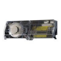
Figure 6. Multiple Fan Shutdown (interconnection of D4120’s): Figure 7. Multiple Fan Shutdown (interconnection of
D4120 to DH100ACDC):
Important Interconnection Notes
• Whenusingtheinterconnectfeature,all interconnected units must be powered using the same independent supply.
• Polaritymustbemaintainedthroughouttheinterconnectwiring.ConnecttheINT+terminalonunit1totheINT+terminalonunit2andso
on. Similarly, connect the INT/AUX- terminal on unit 1 to the INT/AUX- terminal on unit 2 and so on.
• Upto50D4120unitsmaybeinterconnected.
• Upto10DH100ACDCunitsmaybeinterconnected.WheninterconnectingD4120unitswithDH100ACDCunits,threeD4120’smaybesubsti-
tuted for every one DH100ACDC. For example, nine DH100ACDC units may be interconnected with up to three D4120 units. A maximum of 27
D4120 units may be interconnected with one DH100ACDC.
• Allinterconnecteddetectorsaretobepoweredfromthesamesource.
ALARM
AUX OUT –
15
20
(+)
(–)
DUCT DETECTOR
D4120
MHR/MHW (OPTIONAL)
AUDIBLE ALERT
ALARM
AUX OUT –
15
20
(+)
(–)
DUCT DETECTOR
D4120
RA400Z (OPTIONAL)
REMOTE (LED)
ANNUNCIATOR
RED
Figure 8. Wiring diagrams for optional accessories:
H0554-00
10
9
19
20
1
12
15
3
2
1
D4120
APA151/451
(GREEN LED) POWER
FIELD
INSTALLED
JUMPER
1 1
2
+
–
AUX OUT +
AUX OUT –
ALARM
R TEST
ACC +
ACC –
R RESET
7
18
8
17
6
16
14
3
13
5
4
SUP, NO
SUP, C
NOTE: WIRING DIAGRAM SHOWN IS FOR D4120 4-WIRE DUCT SMOKE DETECTOR
SYSTEM EQUIPPED WITHOUT A CONTROL PANEL.
NOTE: A TROUBLE CONDITION IS INDICATED WHEN THE GREEN LED
IS NOT ILLUMINATED.
COMMON
(RED LED) ALARM
Figure 9. Wiring diagram for D4120
to APA151 or APA451:
H0584-00
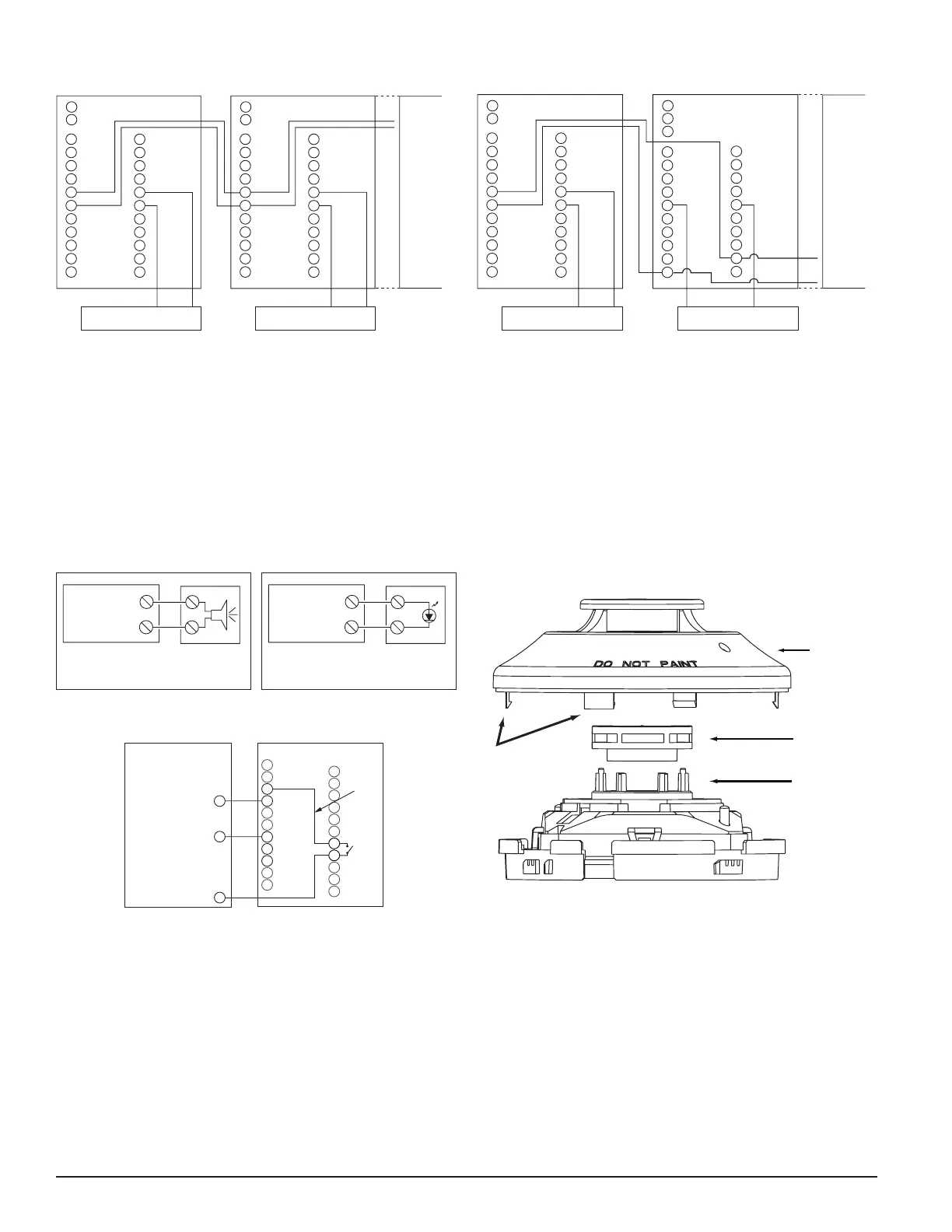
SENSOR
COVER
SENSING
CHAMBER
COVER AND
SCREEN
SENSOR
CHAMBER
COVER
REMOVAL
TA BS
CONTACT RATING 2AMP
Figure 10. Detector sensor exploded view:
C1009-00