a visual indication of power, trouble, and alarm respectively. An optional
strobe (PS24LOW) with a smoke lens can be added to conform to the
codes of certain jurisdictions.
To install the SSK451, connect the device as shown in Figure 12.
[8.2] Measurement Tests
[8.2.1] Air Flow
The D4120 is designed to operate over an extended air speed range of 100 to
4000 FPM. To verify sufficient sampling of ducted air, turn the air handler
on and use a manometer to measure the differential pressure between the
two sampling tubes. The differential pressure should measure at least 0.0015
inches of water and no more than 1.2 inches of water. Because most com-
mercially available manometers cannot accurately measure very low pressure
differentials, applications with less than 500 FPM of air speed may require
one of the following: 1) the use of a current-sourcing pressure transmitter
(Dwyer Series 607) per Section 8.2.2; or 2) the use of aerosol smoke per sec-
tion 8.2.4.
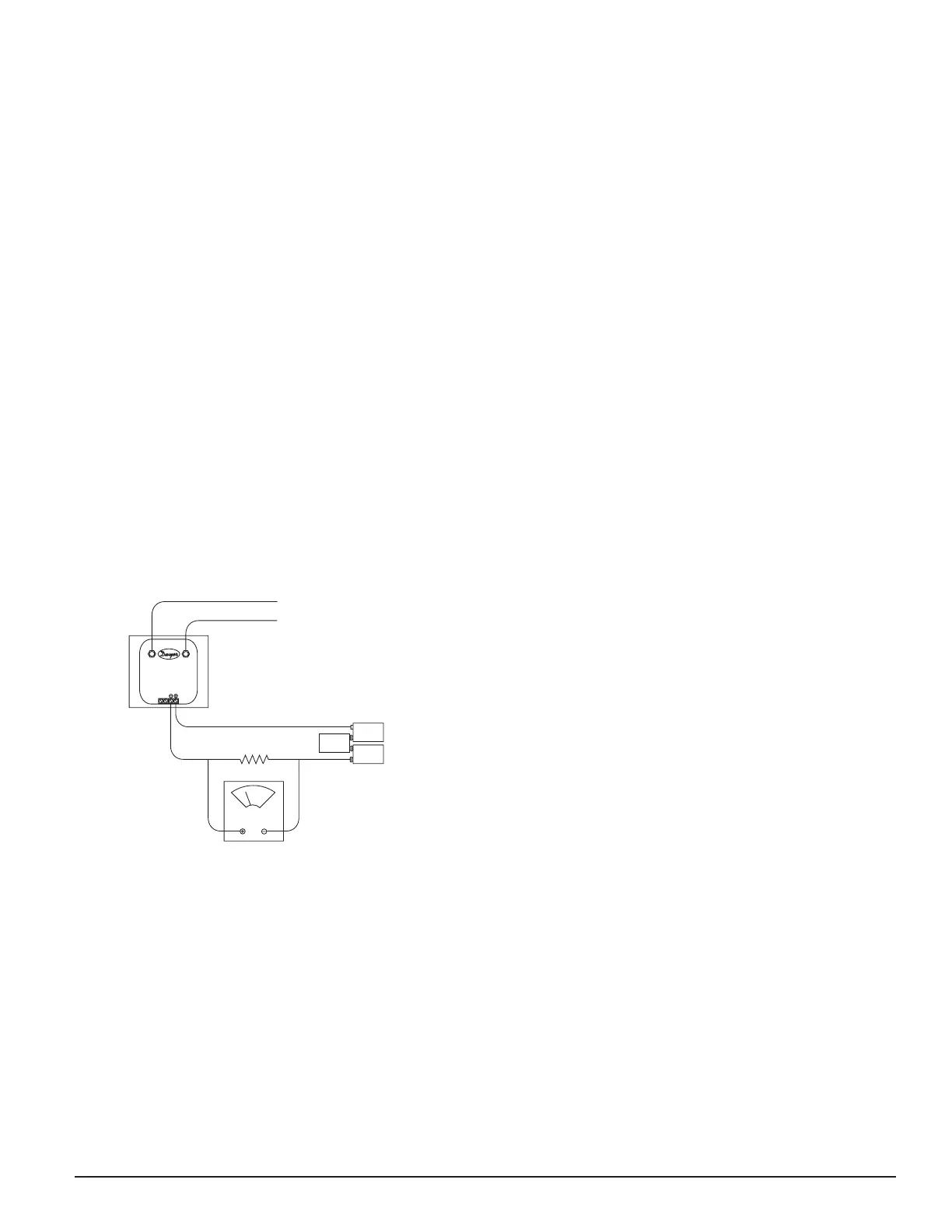
[8.2.2] Low Flow Air Flow Test using Dwyer Series 607 Differential
Pressure Transmitter
Verify the air speed of the duct using an anemometer. Air speed must be at
least 100 FPM. Wire the Dwyer transmitter as shown in Figure 5. Connect
the leads of the meter to either side of the 1000Ω resistor. Allow unit to
warm up for 15 seconds. With both HIGH and LOW pressure ports open to
ambient air, measure and record the voltage drop across the 1000Ω resistor
(measurement 1), 4.00 volts is typical. Using flexible tubing and rubber
stoppers, connect the HIGH side of the transmitter to the sampling tube of
the duct smoke detector housing, and the LOW side of the transmitter to
the exhaust tube of the duct smoke detector housing. Measure and record
the voltage drop across the 1000Ω resistor (measurement 2). Subtract the
voltage recorded in measurement 1 from the voltage recorded in measure-
ment 2. If the difference is greater than 0.15 volts, there is enough air flow
through the duct smoke detector for proper operation.
Figure 5. Procedure for verifying air flow less than 500 FPM:
DIFFERENTIAL
PRESSURE
TRANSMITTER
MODEL #607-01
HIGH
LOW
TO SAMPLING TUBE
TO EXHAUST TUBE
VOLT METER
FLUKE MODEL 87
OR EQUIVALENT
1000 OHM 5% 1 WA TT RESISTOR
9 VOLT
BATTERY
9 VOLT
BATTERY
9 VOLT
BATTERY
15 TO 36VDC
SUPPLY
H0163-01
[8.2.3] Smoke Response Tests
To determine if smoke is capable of entering the sensing chamber, visually
identify any obstructions. Plug the exhaust and sampling tube holes to
prevent ducted air from carrying smoke away from the detector head, then
blow smoke such as cigarette, cotton wick, or punk directly at the head to
cause an alarm. REMEMBER TO REMOVE THE PLUGS AFTER THIS TEST,
OR THE DETECTOR WILL NOT FUNCTION PROPERLY.
[8.2.4] Smoke Entry using Aerosol Smoke
This test is intended for low-flow systems (100-500 FPM). If the air speed
is greater than 500 FPM, use a conventional manometer to measure differ-
ential pressure between the sampling tubes, as described in 8.2.1.
Drill a
1
⁄4˝ hole 3 feet upstream from the duct smoke detector. With the
air handler on, measure the air velocity with an anemometer. Air speed
must be at least 100 FPM. Spray aerosol smoke* into the duct through the
1
⁄4˝ hole for five seconds. Wait two minutes for the duct smoke detector
to alarm. If the duct smoke detector alarms, air is flowing through the
detector. Remove the duct smoke detector cover and blow out the residual
aerosol smoke from the chamber and reset the duct smoke detector. Use
duct tape to seal the aerosol smoke entry hole.
*Aerosol smoke can be purchased from Home Safeguard Industries, Mal-
ibu, CA. Phone: 310/457-5813.
[8.3] Sensitivity Verification
The sensitivity of the sensor is confirmed to be operating within its allow-
able range each time the sensor and power board LEDs blink green every
5 seconds. Note in a maintenance condition the sensor LEDs will blink red
every 5 seconds and power board will blink amber as depicted in Table 1.
The maintenance condition indicates that the sensor is operating outside
its original factory preset sensitivity and shall be cleaned or replaced. See
Section 9 for reference. This is a valid UL test.
[9] Detector Cleaning Procedures
Notify the proper authorities that the smoke detector system is undergo-
ing maintenance, and that the system will temporarily be out of service.
Disable the zone or system undergoing maintenance to prevent unwanted
alarms and possible dispatch of the fire department.
[9.1] Detector Sensor
1. Remove the sensor to be cleaned from the system.
2. Remove the sensor cover by pressing firmly on each of the four re-
moval tabs that hold the cover in place. See Figure 10 on page 6.
3. Vacuum the screen carefully without removing it. If further cleaning is
required continue with Step 4, otherwise skip to Step 7.
4. Remove the chamber cover/screen assembly by pulling it straight out.
5. Use a vacuum cleaner or compressed air to remove dust and debris
from the sensing chamber.
6. Reinstall the chamber cover/screen assembly by sliding the edge over
the sensing chamber. Turn until it is firmly in place.
7. Replace the cover using the LEDs to align the cover and then gently
pushing it until it locks into place.
8. Reinstall the detector.
[9.2] Reinstallation
1. Reinstall the detector in its housing.
2. Restore system power.
3. Perform Detector Check, Section [7.3].
4. Notify the proper authorities testing has been completed and the smoke
detector system is back in operation.
[10] Sensor Replacement (part no. 2D51)
1. Remove the sensor head by rotating counterclockwise.
2. Pull gently to remove it.
3. To replace the sensor head, align the mounting features and rotate
clockwise into place.
SS-300-000 5 I56-2967-000R
 Loading...


