Install the inlet tube as follows:
1. Drill a
3
⁄4 ″ hole in the duct directly opposite the hole
already drilled for the inlet tube. Make sure the hole is 1
to 2″ below the inlet hole on the opposite side of the
duct to allow for moisture drainage.
2. Slide the inlet tube with the flange into the housing bush-
ing that meets the air flow first. Position the tube so that
the arrows point into the air flow. Secure the tube flange
to the housing bushing with two #6 self-tapping screws.
3. From inside the duct, couple the other sections of the
inlet tube to the section already installed using the
1
⁄2 ″
conduit fittings supplied. Make sure that the holes on
both of the air inlet tubes are lined up and facing into
the air flow.
4. Trim the end of the tube protruding through the duct so
that 1 to 2″ of the tube extend outside the duct. Plug this
end with the end plug and tape closed any holes in the
protruding section of the tube. Be sure to seal the duct
when the tube protrudes.
NOTE: An alternate method to using the ST-10 is to use
two ST-5 inlet tubes. Remove the flange from one
of the tubes and install as described above. After
the installation, use electrical tape to close off
some of the sampling holes so that there are a total
of 10 to 12 holes spaced as evenly as possible
across the width of the duct.
NOTE: Air currents inside the duct may cause excessive
vibration, especially when the longer sampling
tubes are used. In these cases a 3″ floor flange
(available at most plumbing supply stores) may be
used to fasten the sampling tube to the other side
of the duct. When using the flange/connector
mounting technique, drill a 1″ to 1
1
⁄4 ″ hole where
the flange will be used.
[5.4.3] Modifications of Inlet Sampling Tubes
There may be applications where duct widths are not what
is specified for the installation. In such cases, it is permis-
sible to modify an inlet sampling tube that is longer than
necessary to span the duct width.
Use a 0.193-inch diameter (#10) drill and add the appropri-
ate number of holes so that the total number of holes
exposed to the air flow in the duct is 10 to 12. Space the
additional holes as evenly as possible over the length of the
tube.
NOTE: This procedure should only be used as a temporary
fix. It is not intended as a permanent substitute for
ordering the correct length tubes.
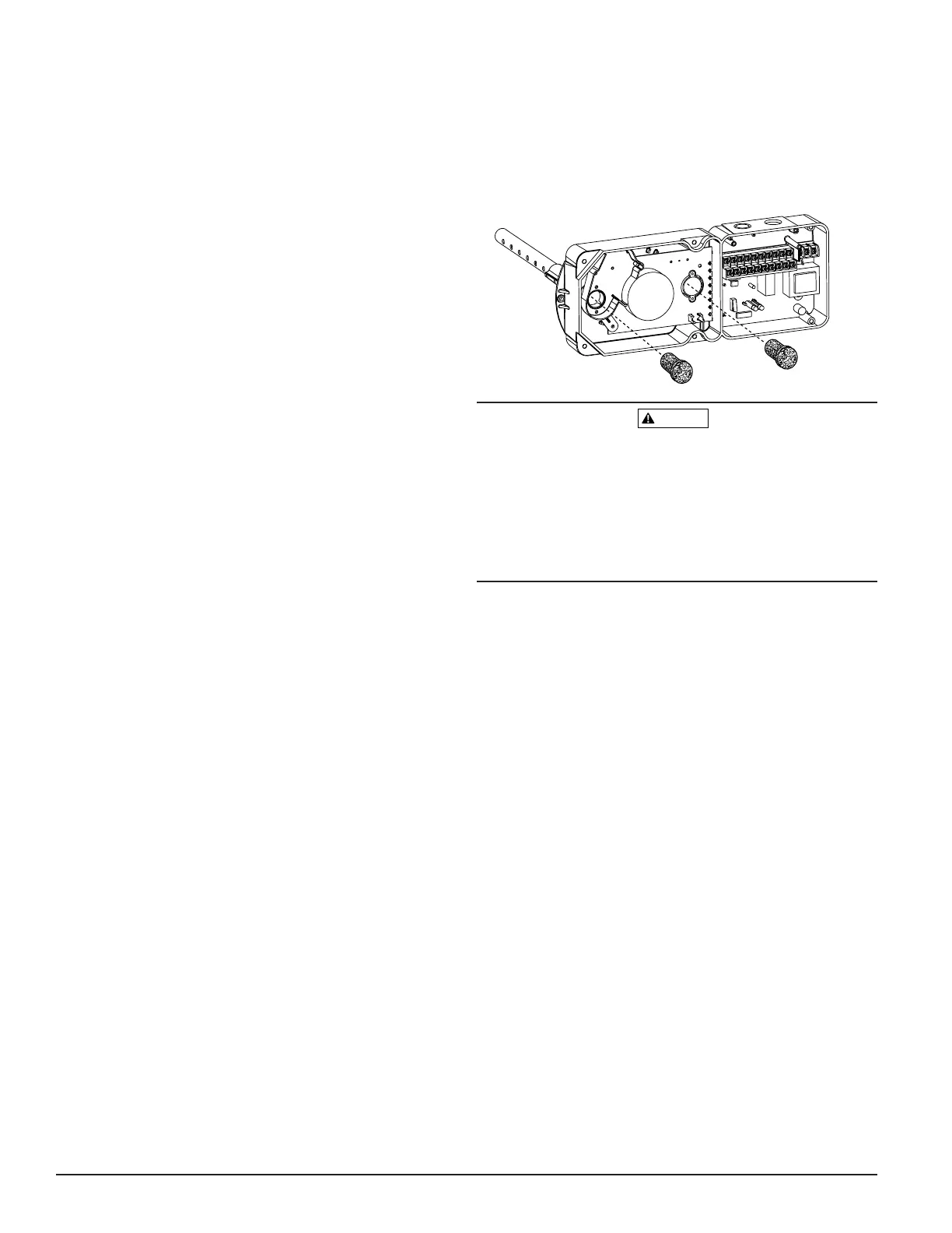
[5.5] Install The Filters
To install the sampling tube filters, simply push the filters
into the sampling and exhaust tube holes, as shown in
Figure 6. If a metal sampling tube is used, install the filters
over the tube ends.
Figure 6. Sampling tube filter installation:
Filters require periodic cleaning or replacement, depending
on the amount of dust and dirt accumulated. Visually
inspect the filters at least quarterly; inspect them more
often if the dust accumulation warrants it. See Section [6]
for more information. Replacement filters can be ordered
from System Sensor, 3825 Ohio Ave., St. Charles, IL 60174.
(Exhaust tube/intake tube filter P/N F36-09-11)
[5.6] Field Wiring
Wiring Installation Guidelines
All wiring must be installed in compliance with the
National Electrical Code and the local codes having juris-
diction. Proper wire gauges should be used. The conduc-
tors used to connect smoke detectors to control panels and
accessory devices should be color-coded to prevent wiring
mistakes. Improper connections can prevent a system from
responding properly in the event of a fire.
For signal wiring, (the wiring between interconnected
detectors or from detectors to auxiliary devices), it is
usually recommended that single conductor wire be no
smaller than 18 gauge. The duct smoke detector terminals
accommodate wire sizes up to 12 gauge.
Smoke detectors and alarm system control panels have
specifications for allowable loop resistance. Consult the
control panel manufacturer’s specifications for the total
loop resistance allowed for the particular model control
panel being used before wiring the detector loop.
D200-14-00 4 I56-0084-00
 Loading...