D900-02-00 3 I56-655-03
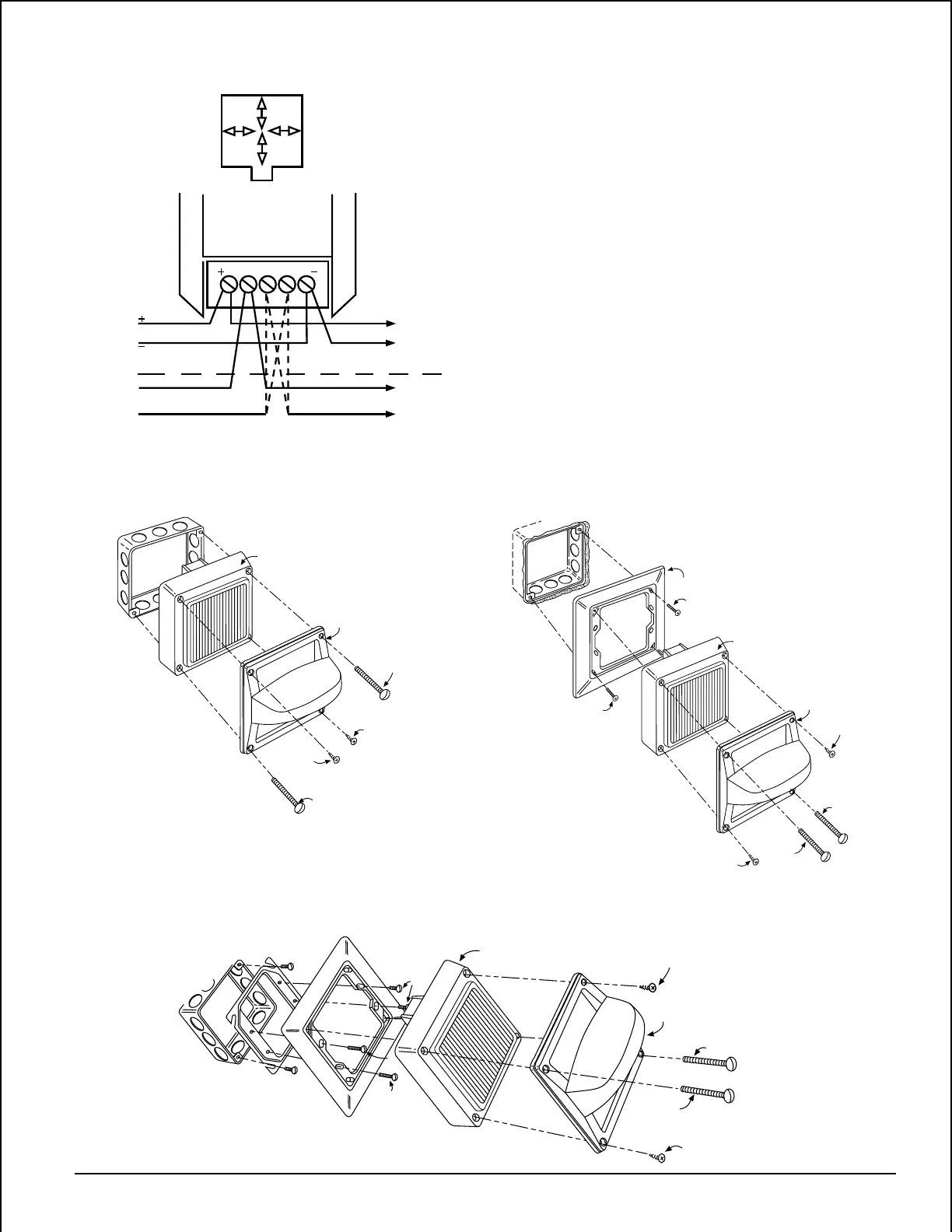
C. Semiflush Wall Mount
(a) System Sensor semiflush mounting plates are
shipped with #8 nuts already installed from the
back.
(b) Attach the semiflush mounting plate to a standard 4-
inch square electrical box using the two 8-32 X 5/8"
slotted screws, provided, at diagonally opposite cor-
ners, as shown in Figure 4.
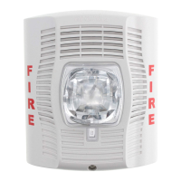
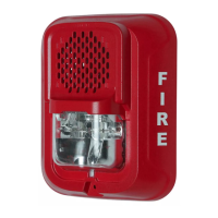
(c) Wire the speaker/strobe as described in Electrical and
mount it on the plate using the two 8-32 X 1-7/16"
slotted screws in diagonally opposite corners. Thread
a #8 sheet metal screw into each of the two remaining
holes in the speaker/strobe.
D. Plaster Ring Mount
See Figure 5. Follow the Semiflush Wall Mount proce-
dure, except attach the semiflush plate to the electrical
box, using the two 6-32 X 5/8" screws.
6-32x5/8
V400
8-32x1-7/16
#8 Sht. Mtl.
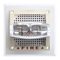
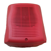
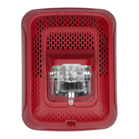
Signal Strobe
8-32x1-7/16
#8 Sht. Mtl.
6-32x5/8
8-32x5/8
Figure 5. Plaster ring mount:
A78-1799-01
8-32x1-7/16
#8 Sht. Mtl.
#8 Sht. Mtl.
8-32x1-7/16
Signal Strobe
V400
Figure 3. Surface wall mount:
A78-1794-02
V400
8-32x1-7/16
#8 Sht. Mtl.
Signal Strobe
8-32x1-7/16
#8 Sht. Mtl.
MP-SF
8-32x5/8
8-32x5/8
Figure 4. Semiflush wall mount:
A78-1796-02
Figure 2:
2W
1W
1/4W
1/2W
COM 25 70.7
FROM
PANEL OR
PREVIOUS
DEVICE
STROBE
25 OR
70.7V
TO
NEXT
DEVICE
OR
EOL
TO
NEXT
DEVICE
OR
EOL
A78-1792-01
Technical Manuals Online! - http://www.tech-man.com