6
Step 5. Installing Grommet and Tubing
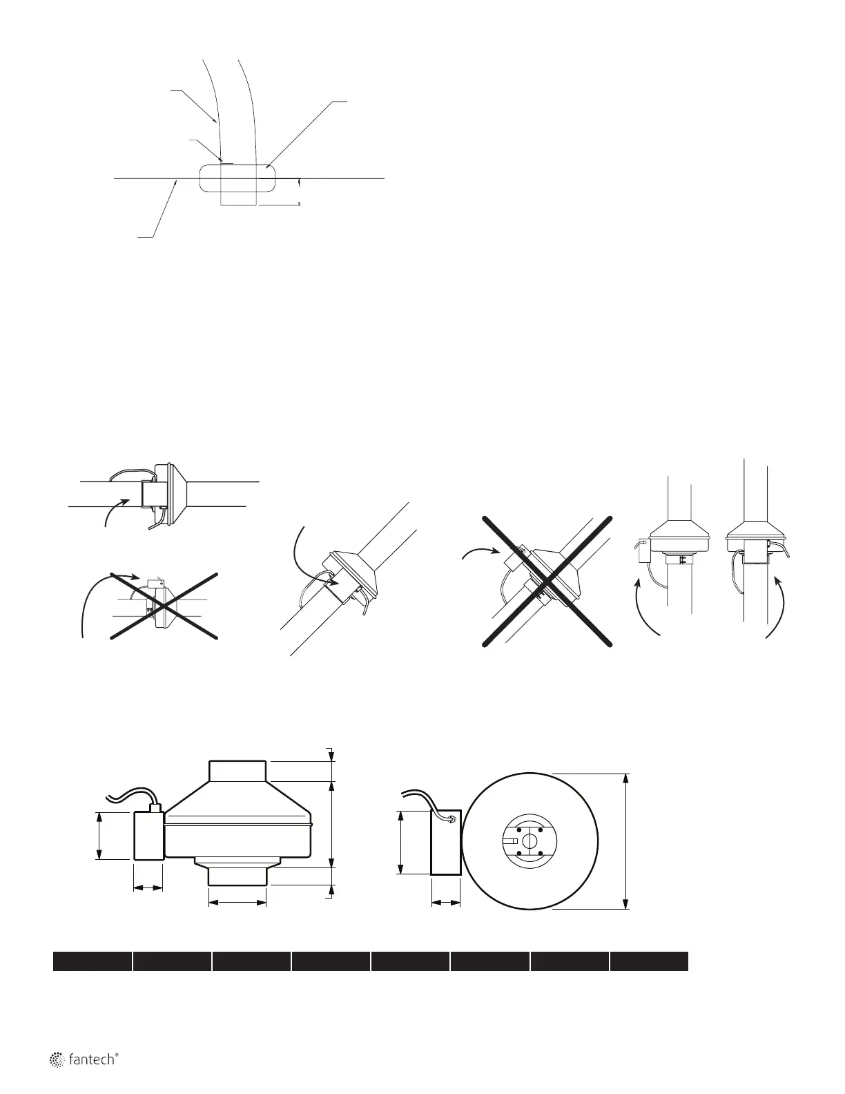
Do not connect tubing in such a manner as to allow condensation from
the duct to collect in the tubing.
First, drill a 3/8 inch (10 mm) to 7/16 inch (11 mm) diameter hole in
the duct wall. Carefully insert the grommet into the hole. (Drilling a
metal duct may produce burrs. Be careful not to be cut or pricked by
the burrs or the duct.) Next, force one end of the tubing over the nipple
on the control. Make a mark a distance of 1/2 inch (13 mm) from the
other end of the tubing. Slide this end of the tubing through the center
of the grommet up to the mark as illustrated.
Step 6. Powering the DPV22-2
Plug the power cord into a nearby 120V, 1~ electrical receptacle.
1/4" (6 mm) Max.
Duct Wall
Grommet
Tubing
1/2" (13 mm) Mark on Tubing
Control Correct
in all Positions
Incorrect
Control
Positioning
Incorrect Control Positioning
Correct Control Positioning
Correct Switch Positioning - Diaphragm Positioned Vertically
Vertical Duct
Angled Duct
Horizontal Duct
Pressure Switch Positioning
Tubing
1/2" (13 mm) Mark on
Tubing
Grommet
Duct Wall
1/4" (6 mm) Max.
Correct Control
Positioning
Dimensions
All dimensions in inches (mm)
A C D E F G H I
3 7/8 (98) 9 3/4 (248) 6 1/4 (159) 1 (25) 1 (25) 2 (51) 3 7/8 (98) 3 3/4 (95)