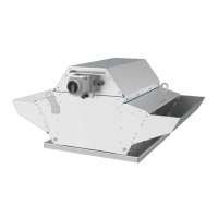
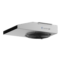
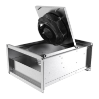
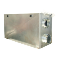
This document describes the DVG EC F400 Roof fans, which are designed for both normal ventilation and smoke/heat extraction. These fans are suitable for outdoor rooftop installations and are connected to a duct system.
Function Description
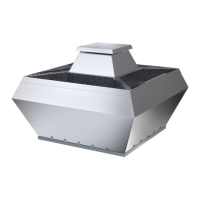
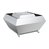
The DVG EC F400 Roof fans are versatile units equipped with an EC motor, a safety switch, and a casing made from seawater-resistant aluminum, which also includes integrated bird protection. They are capable of continuous operation, handling clean or contaminated air with temperatures ranging from -20 to 120 °C and up to 95% air humidity. The ambient temperature for operation is specified from -20 to 70 °C.
In the event of a fire, these fans can also function for smoke and hot gas extraction, capable of resisting temperatures up to 400 °C for 120 minutes. However, if used for smoke or hot gas extraction, the fan must be replaced afterward.
The DVG-H models feature horizontal air exhaust and are designed for roofs with a snow load classification of SL1000. The DVG-V models have vertical air exhaust and a snow load classification of SL 0.
All DVG EC fans support communication via MODBUS. For sizes 355-450, the casing incorporates a swing-out function, providing easy access to the impeller for maintenance.
The product is not supplied with a speed control or installation equipment, which are available as accessories. It is not suitable for transporting air containing explosive, flammable, or aggressive media, nor for locations with a risk of explosion.
Important Technical Specifications
The technical specifications vary by model and dimension. Key parameters include:
Type Designation:
- Product Name: DVG-H, DVG-V
- Dimensions: Available in sizes 355, 450, 560, 630, 800.
- Fire Protection Class: F400 - 400°C/2h for all models.
- Motor Type: EC (electronically commuted).
- 1-phase, 230 V for certain models.
- 3-phase, 400 V for certain models.
Name Plate Information (examples):
- Connection: Voltage (V), Frequency (Hz)
- Input Power: kW
- Nominal Motor Power: kW
- Current: A
- RPM: min⁻¹
- Max. Airflow: m³/h
- Weight: kg
- Motor IP Class, Insulation Class
- Fire Classification; Snow Load
- Application; Response Delay
- Transportation Air Temperature: °C
- Manufacturer; Rotation Direction Arrow
- Certifications
- Outlet
- Production Address
Electrical Data:
- Refer to the name plate for specific electrical connection details (e.g., 230V, 1-phase or 380-480V, 3-phase).
- EC motors have integrated motor protection.
- Leakage current to earth for EC motors is ≤3.5 mA.
Product Dimensions (in millimeters):
Dimensions are provided for DVG-H and DVG-V models, including ØA, ØB, ØC, D, E, F, ØG, ØH, ØI, ØJ, K, and L. For example:
- DVG-H 355: ØA (6XM8), ØB (438), ØC (12), D (450), E (30), F (598), ØG (224), ØH (310), ØI (400), ØJ (240), K (708), L (486).
- DVG-V 800: ØA (16XM8), ØB (860), ØC (14), D (1050), E (40), F (1255), ØG (581), ØH (690), ØI (800), ØJ (240), K (2024), L (803).
Differential Pressure Monitoring (K-factor for Impeller F400):
- 355 EC - XL - F400: 135
- 450 EC - XL - F400: 220
- 560 EC - XL - F400: 330
- 630 EC - XM - F400: 485
- 800 EC - XL - F400: 830
Airflow calculation: Air volume = k * SQRT(dp) in m³/h, where dp = p2-p1. The K-factor is usable over 50% max. airflow for each fan size.
Usage Features
Installation:
- Roof Curb: Systemair recommends installing the product with a roof curb (available as an accessory). A temperature-resistant sealing tape should be applied between the base plate and the roof. The roof curb height should be a minimum of 250 mm above the rooftop to prevent snow from covering the fan.
- Duct Connection: Flexible connections are recommended to reduce vibrations. If installing near a duct bend, ensure a minimum distance (A) of 2.5 times the duct diameter (B) to prevent vibrations, unwanted noise, and decreased air pressure.
- Free Suction: If installed with free suction, a protection grille is necessary, adhering to safety distances specified in DIN EN ISO 13857 and DIN 24167-1.
- Service Switch: A service switch is installed on the fan casing. For sizes 355-450, the swing-out casing allows access to the impeller. The service switch can be locked in the "on-position" with a padlock to guarantee operation in case of fire.
- Cabling: Cables must ensure uninterrupted power supply in case of fire or extreme heat. Use temperature-resistant cable protection if necessary. Do not run cables on the fan casing due to high temperatures during smoke/heat extraction. All cable glands must be tight to prevent leaks.
- Location: Install in a clean, dry location with sufficient space for commissioning, troubleshooting, and maintenance. The installation surface must support the product's weight.
Operation:
- Starting: Set the 0-10 V signal to "0" with the speed controller, set the safety switch to ON and wait 5 seconds, then adjust fan speed.
- Stopping: Set the speed controller to OFF, then set the safety switch to OFF.
- Emergency Stop: Set the installed safety switch to the OFF position.
- Continuous Operation: To prevent condensation in cold corners, keep the fan in constant operation.
- EC Motor Control: EC motors are controlled via a stepless 0-10 V signal. Do not use power supply for the speed controller.
- Fire Mode: The product has a built-in controller with a fire mode function, allowing activation of "firemode MAX" by default. In fire mode, all alarms are ignored, and the fan operates at maximum speed until motor failure or loss of electrical supply. Fire mode is activated via a digital input (open contact) and reset via a digital input (close contact) and a ~2 min power cut.
Maintenance Features
Maintenance Schedule (based on continuous operation):
Usual Operation Conditions:
- Every 6 months:
- Visually examine for damage, corrosion, dirt.
- Examine fan impeller for damage and imbalance.
- Clean the product and ventilation system.
- Check and tighten all fasteners.
- Ensure correct operation of product and components.
- Measure power consumption and compare to name plate.
- Ensure electrical and mechanical protective equipment operates correctly.
- Ensure name plates are readable.
- Examine cable connections and glands.
- Examine flexible connections for damage.
- Every year:
- Same checks as every 6 months.
Unusual Operation Conditions (e.g., ambient temperature >30°C or <-10°C, large temperature changes, very contaminated air):
- Every 3 months:
- Visually examine for damage, corrosion, dirt.
- Examine fan impeller for damage and imbalance.
- Clean the product and ventilation system.
- Every 6 months:
- Same checks as every 3 months.
- Check and tighten all fasteners.
- Ensure correct operation of product and components.
- Measure power consumption and compare to name plate.
- Ensure electrical and mechanical protective equipment operates correctly.
- Ensure name plates are readable.
- Examine cable connections and glands.
- Examine flexible connections for damage.
- Every year:
- Same checks as every 6 months.
Cleaning:
- Do not use high-pressure washers, steel brushes, or sharp objects.
- Do not bend fan impeller blades or move balance weights.
- Remove dirt from the fan and duct.
- If accessible, clean the fan impeller with a moist cloth or soft brush regularly.
Troubleshooting:
- A dedicated section provides solutions for common issues like unbalanced impeller, dirt, motor damage, incorrect wiring, insufficient air output, and unusual noise.
- For issues like an overheated motor, winding resistance values are provided for different models (e.g., 355 EC - XL - F400: 2.57 Ohm, 800 EC - XL - F400: 0.41 Ohm).
Spare Parts:
- Contact Systemair support for information and orders. Always use original Systemair spare parts and include the product's serial number when ordering.
Disposal:
- The product follows the WEEE directive and must be recycled at an approved disposal location for electrical and electronic equipment. Disassemble in the reverse order of installation and recycle parts and packaging according to local and national requirements.
Warranty:
- Warranty claims require a written maintenance plan and commissioning report. The warranty is applicable if the product is correctly installed and operated, instructions are obeyed, maintenance instructions are followed, and if not continuously operated, it is operated for a minimum of 1 hour per month.