EasyManuals Logo

SystemAir K Series User Manual

SystemAir K Series
36 pages
To Next Page IconTo Next Page
To Previous Page IconTo Previous Page
Page #29 background imageLoading...
Page #29 background image
EC-Vent
Demand control for up to 5 external sensors, 2 fans, damp-
ers, heaters and coolers.
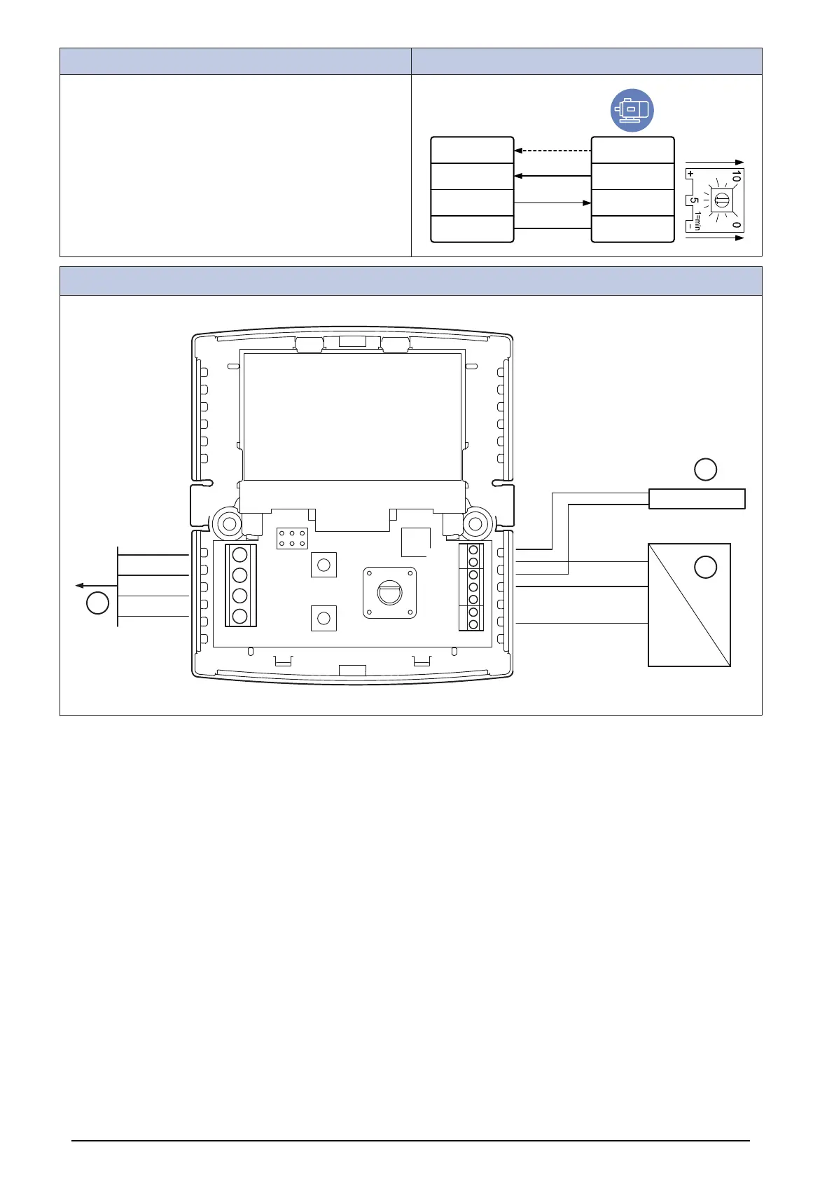
The EC vent system has 2 units. The control board (CB) and
the room unit (RU). Connect the fan to the control board and
remove the internal potentiometer.
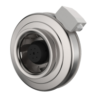
EC-Vent
IN/RPM
PWM
IN/10V
OUT/PWN
GND
TACH
optional
+10V
0...10V/PWM
GND
Room Unit (RU)
Br + 24VDC
Y +0-10V
Gr-
Bl (GND)
R+ 24VDC
Y +0-10V
W -
CB
A
B
GND
24V
REF
T1
I2
I1
24V
C
B
A
27

Table of Contents

Other manuals for SystemAir K Series

Questions and Answers:

Question and Answer IconNeed help?

Do you have a question about the SystemAir K Series and is the answer not in the manual?

SystemAir K Series Specifications

General IconGeneral
BrandSystemAir
ModelK Series
CategoryFan
LanguageEnglish

Related product manuals