6
| Installation
Position Description
R
Right hand model (Supply air connection is situated on the right hand side of the unit viewed from
the front)
L
Left hand model (Supply air connection panel is situated on the left hand side of the unit viewed
from the front)
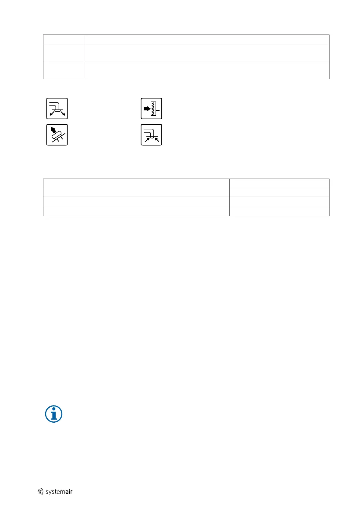
Symbol
Description
Symbol
Description
Supply air
Outdoor air
Exhaust air
Extract air
5.5.4 Power consumption and fuse size
Re-heater
1670 W
Fans 340 W
Total power consumption
2010 W
Fuse 13 A
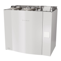
6 Installation
This section describes how to install the unit correctly. To ensure a proper and fail-free operation, it is important that
the unit is installed according to these instructions.
6.1 Unpacking
Verify that all ordered equipment are delivered before starting the installation. Any discrepancies from the ordered
equipment must be reported to the supplier of Systemair products.
6.2 Where/how to install
The SAVE VTR 500 should preferably be installed in a separate room (e.g. storeroom, laundry room or similar.).
When choosing the installation position, consideration must be taken that the unit requires regular maintenance. Leave
free space for opening of the front hatch in order to perform service and maintenance on components inside the unit.
The SAVE VTR 500 is supplied with approximately 2 m cable and plug for 230V, single phase earthed connection placed
at the bottom of the unit.
Recommended installation location for the outdoor air intake is the northern or eastern side of the building and with a
distance to openings for discharge of stale ventilation air, kitchen ventilator, central vacuum system, waste water drain-
age and other pollution sources like exhaust from traffic etc. Stale discharge air should ideally be led via a roof unit to
the outside and with a good distance to any outdoor air intake, windows etc.
6.3 Installation procedure
Note:
It is recommended to remove the heat exchanger before the installation to make the unit lighter. The heat
exchanger weighs about 16 kg. How to remove the heat exchanger, see chapter 6.3.1 steps 1 through 3.
211477 | A001
 Loading...