Рис. 3 Fig. 3
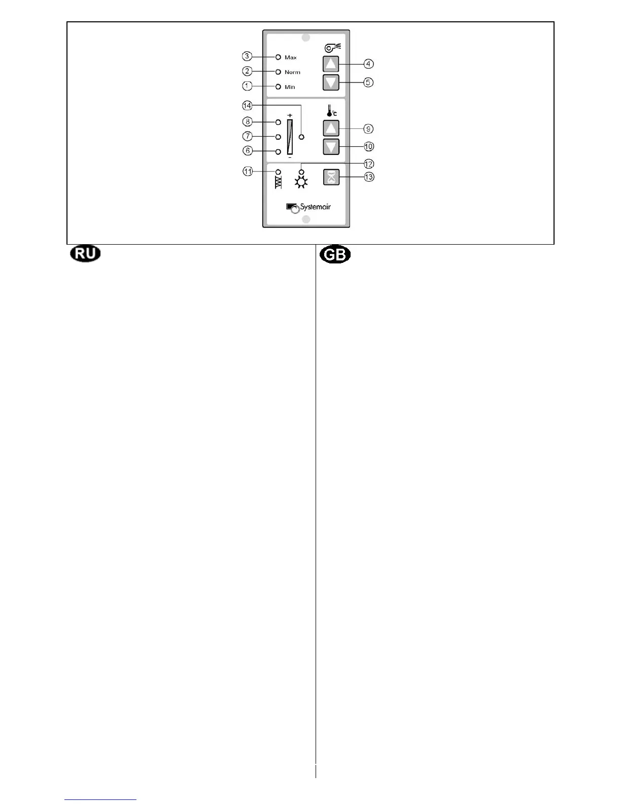
Принцип действия (Рис.3)
Следующими функциями агрегата можно
управлять посредством одной и более
панелей управления:
Расход водуха (скорость вентилятора)
Кнопки для выбора расхода водуха в 3
ступени. Выбор скорости вентилятора
проиводится кнопками (4) и (5). Индикаторы
(1), (2) и (3) указывают текущее значение.
Min (1) Минимальная вентиляция.
Испольуется в выходные,
праздничные дни.
Norm (2) Нормальная вентиляция. Расход
воздуха для этого режима
задается на контрольной панели
(высокий/низкий). См. Инструкцию
по монтажу.
Max (3) Усиленная вентиляция. Когда
требуется дополнительная
вентиляция помещения.
Температура приточного воздуха
Кнопки для выбора температуры приточного
воздуха (5 ступеней). Уменьшение/увеличе-
ние температуры приточного воздуха произ-
водится кнопками (9) и (10). Индикаторы (6),
(7) и (8) указывают текущую выбранную
температуру.
Ступень 1 Индикатор (6) горит
Ступень 2 Индикаторы (6) + (7) горят
Ступень 3 Индикатор (7) горит
Ступень 4 Индикаторы (7) + (8) горят
Ступень 5 Индикатор (8) горит
Когда утилизации тепла вытяжного воздуха
недостаточно, чтобы достичь требуемой
температуры приточного воздуха, автомати-
чески включается воздухо-нагреватель.
OPERATION (Fig. 3)
The unit is controlled from one or more
remote controllers, with the following
functions:
Airflow (Fan speed)
Switches for choise of airflow in 3 steps.
Increase/ decrease fan speed by pressing
the switches (4) and (5) alternatively. Lamp
signals (1), (2) and (3) show set airflow.
Min (1) Minimum ventilation. To be used
during holidays or when the
building is not in use.
Norm (2) Normal ventilation adapted to the
building. Airflow for normal
ventilation can be chosen
(high/low) by means of setting on
the control panel (see installation
instructions, Commissioning).
Max (3) Forced ventilation. Is used when
extra airflow is required.
Supply air temperature
Switches for choise of inlet air temperature in
5 steps. Supply air temperature is increased/
decreased by pressing switch (9) and (10)
alternatively. Lamp signals (6), (7) and (8)
show set supply air temperature.
Step 1 Lamp (6) lights
Step 2 Lamp (6) and (7) light
Step 3 Lamp (7) lights
Step 4 Lamp (7) and (8) light
Step 5 Lamp (8) lights
When heat recovery from the extract air is in-
sufficient to obtain set supply air temperature,
an electrical heater battery will automatically
be switched on.
5
Индикатор (14) горит, когда воздухонагрева- Lamp signal (14) will light up when the heater