13
CAUTION
Be cautious when installing the connective pipe. Do not let any
air, dust or other foreign substance enter the system.
Pipe connections should be conducted after the indoor and
outdoor unit are fixed.
Connective pipes must stay dry during installation.
Connective copper pipes must be wrapped with an insulation
layer (at least 9 mm thick).
The temperature of the refrigerant circuit will be high. Keep the
interconnection cable away from the copper tube
6.5 Air expels
Apply the vacuum pump to expel air from refrigerant charging
vent from the air side in the outdoor unit.
Do not apply the refrigerant inside the indoor unit for vacuum
air.
6.6 Open valve
Use a 5-mm hexagon wrench to open the valve spool of the
indoor and outdoor units.
6.7 Leak detection
Use soapy water to check whether gas is leaking from the
adapters
6.8 Thermal insulation
To install the thermal insulation for the air side and liquid side
piping. Complete insulation is required for the air side and liquid
side piping because the ambient temperature is very low in
cooling mode.
1) Thermal insulation of at least 120
°C material is required for the
air side piping.
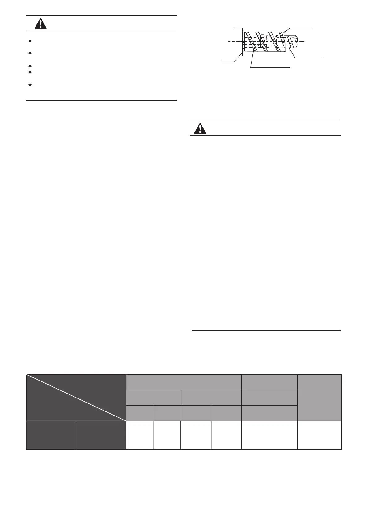
2) Apply the attached thermal insulation material to wrap the
connective part of the indoor piping tightly without any gaps.
Fig.6-6
Unit body
Subsidiary belt for the
thermal insulation pump
Field piping side
Cut top-down
7. WIRING
CAUTION
1) Special power must be applied within the rated voltage
range. The external circuit of this air conditioner must be
grounded. The power cable of the outdoor unit must be jointed
with external grounding wire and reliable.
2) Wiring up the electrics must be performed by professionals
and completed according to the wiring label.
3) Fixing circuit must be wired with an 11-pole disconnection
device with at least 3 mm switching distance from contact.
4) Set the electrical leakage device according to national
regulations.
5) Power cables and signal wires must be arranged in an
ordered manner so they do not interfere with each other or
come into contact with connective pipes and the body of valves.
6) The attached connective wire is 10 m. If this is not long
enough, replace it with a longer one at the same specifications.
Normally, do not overlap the two wires, except for welding them
and insulating them with an adhesive band.
7) An all-pole disconnection device, which has at least 3 mm
away from all poles and a residual current device (RCD) with a
rating of above 10 mA, must be incorporated in the fixed wiring
scheme and comply with national regulations.
8) When the wiring is completed, start up the power once you
have confirmed that all wires are correctly connected and fix
tightly.
7.1 Electrical wiring
Item
Model:
2800W-14000W
Power supply for the indoor part
Power supply:
Signal-phase
220-240 V~ 50 Hz
220-240 V~ 50/60 Hz
Power switch
Capacity
Safety
fuse
15A
15A
Power cable
≤
20 m
≤
50 m
2X4.0 mm
2
2X2.5 mm
2
Connect wiring
Signal wire for the
indoor and outdoor units
Wire diameter
Ground Line
Signal line
2.0 mm
2
Shielded wire
3 X 0.75 mm
2
7.2 Power specifications
The power cable specifications are as follows. Too low power capacity may overheat the piping and burn out the unit.
Table 7-1
 Loading...