F-26277-7 © Copyright 2006 TAC All Rights Reserved. 7
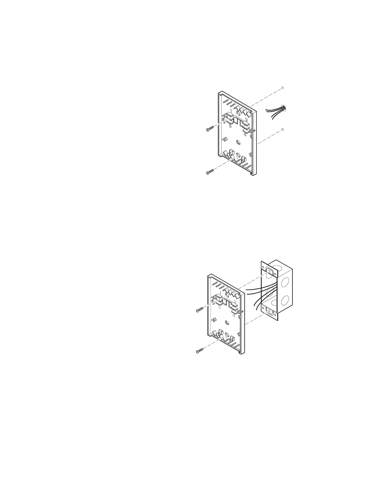
Direct-wall Mount
1. Use mounting dimensions shown in Figure-1.
2. Feed S-Link wires through base plate.
3. If required, feed LON wires through base plate.
4. Using two appropriate screws (use drywall anchors as necessary), mount base plate to
wall (Figure-3).
Figure-3 Direct-wall Mounting.
2 x 4 Electrical Box Mount
1. Use mounting dimensions shown in Figure-1.
2. Feed S-Link wires from electrical box through base plate.
3. If required, feed LON wires through base plate.
4. Using two 6-32 x 5/8 in. flat head screws (not provided), mount base plate to electrical
box (Figure-4).
Figure-4 2 x 4 Electrical Box Mounting.
 Loading...