INSTRUCTION MANUAL
36
Capacity chart in millimeters
Use the capacity charts to determine the maximum wall-thickness of the
tube and to select the right T-DRILL head.
Instructions for the use of the capacity charts:
1. Use the unit of measure that is correct for you: the measures of the
charts are in both millimeters and in inches.
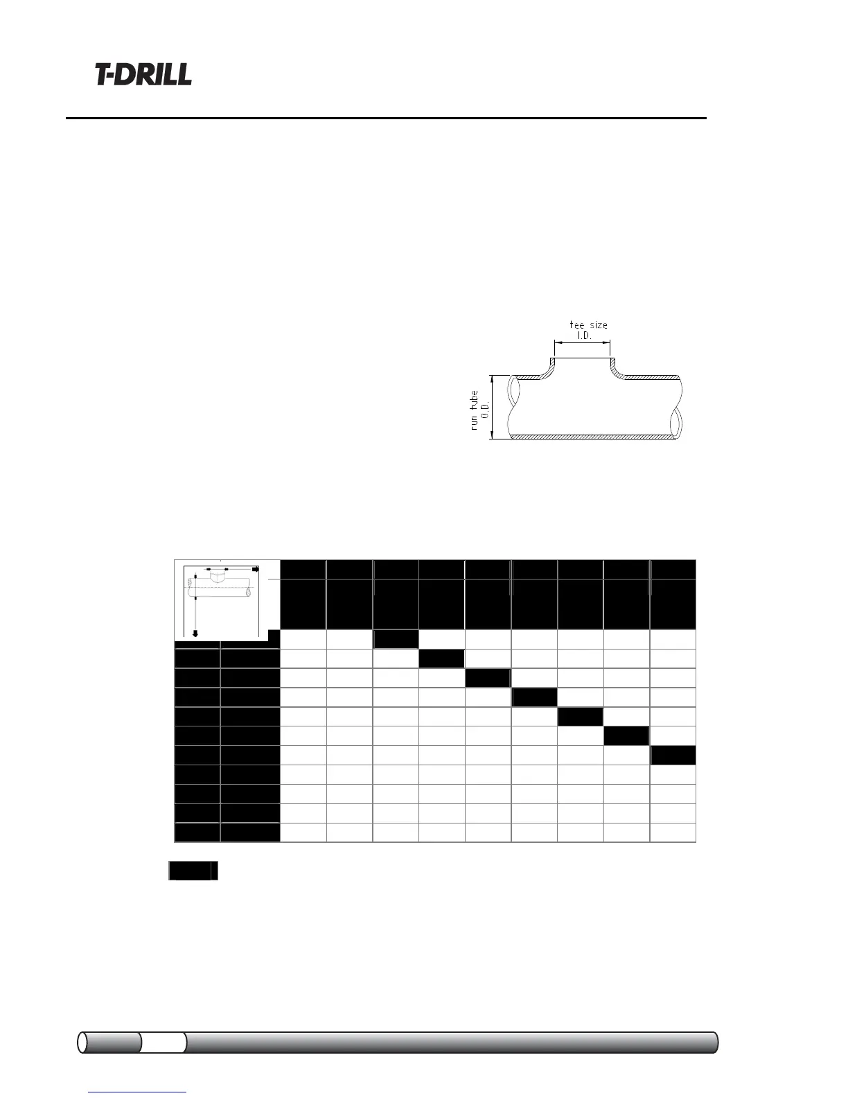
2. From the horizontal black row, find
the tee size you need (inner
diameter), and from the vertical black
column the outer diameter of your
run tube.
3. The intersection of the horizontal and
vertical rows will show you the
maximum wall-thickness of the tube.
This thickness is not to be exceeded.
Capacity charts for forming tees in copper tubes
Max wall-thicknesses (mm)
10 12 15 18 22 28 35 42 54
1/4” 3/8" 1/2" 5/8" 3/4" 1" 1¼" 1½" 2"
15 1/2" 1.0 1.2 1.2
18 5/8" 1.0 1.2 1.5 1.2
22 3/4" 1.0 1.2 1.5 1.5 1.5
28 1" 1.0 1.2 1.5 1.5 1.5 1.5
35 1¼" 1.0 1.2 1.5 1.5 1.5 1.5 1.5
42 1½" 1.0 1.2 1.5 1.5 1.5 1.5 2.0 2.0
54 2" 1.0 1.2 1.5 1.5 1.5 1.5 2.0 2.0 2.0
64 2½" 1.0 1.2 1.5 1.5 1.5 1.5 2.5 2.5 2.5
76,1 3" 1.0 1.2 1.5 1.5 1.5 1.5 2.5 2.5 2.5
88,9 3½" 1.0 1.2 1.5 1.5 1.5 1.5 2.5 2.5 2.5
108 4" 1.0 1.2 1.5 1.5 1.5 1.5 2.5 2.5 2.5
= Annealing before forming the tee is recommended!
 Loading...