2 I/O Modules in the TAC Xenta 400 series TAC Xenta, TAC Xenta® 400 I/O Modules
14 (48) TAC AB, Dec 2004
0-004-7771-3 (EN)
A number of controllers and I/O modules can form a local network and
exchange data.
The TAC Xenta OP operator panel is used to give the user access to cer-
tain parameters and make it possible to present alarms without commu-
nicating with a central system. The most important functions of the
operator panel are status monitoring, adjustment of setpoints and time
channels and the display of alarms.
A maximum of two OPs may be connected to each controller.
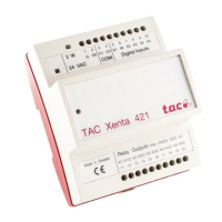
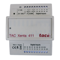
The I/O modules are used as expansion modules for the TAC Xenta
controllers, connected to these via the common TP/FT-10 network.
The modules have different I/O configurations to suit different applica-
tions. Some models have indicators for the digital input status and a
manual override for the digital or analog outputs. An overview of the
available models is shown below.
Table 2.1: Available I/O modules and their I/O configuration
I/O Module
TAC
DI
DI
status
DO
DO
override
UI TI AO
AO
override
Xenta 411 10 - - - - - - -
Xenta 412 10 10 - - - - - -
Xenta 421 4 - 5 - - - - -
Xenta 422 4 4 5 5 - - - -
Xenta 421A - - 5 - 4
a
-- -
Xenta 422A - 4
b
554
a
-- -
Xenta 451 - - - - 4
c
42 -
Xenta 452 - 4
b
--4
c
42 2
Xenta 451A - - - - 8
a
-2 -
Xenta 452A - 8
b
--8
a
-2 2
Xenta 471 - - - - 8
d
-- -
Xenta 491 - - - - - - 8 -
Xenta 492 - - - - - - 8 8
a. DI, 0–10 V DC or 0–20 mA, 1.8/10 kohm TI
b. Status indication only when the corresponding universal inputs (UI) are being used as digital
inputs.
c. DI, 0–10 V DC, 1.8 kohm TI
d. 0–10 V DC or 0–20 mA