TAC Xenta, TAC Xenta® 400 I/O Modules 4 Installation
TAC AB, Dec 2004 39 (48)
0-004-7771-3 (EN)
Connections
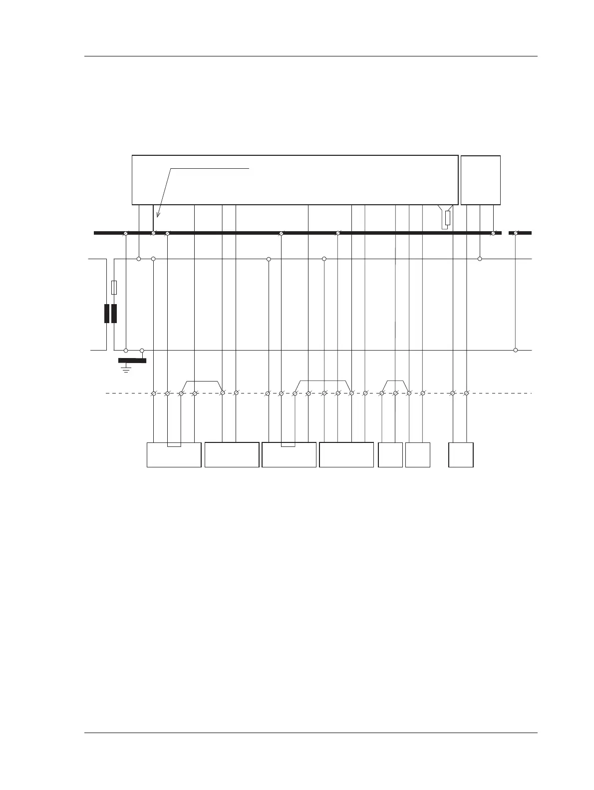
When cabinet mounting is used, jumpers may be used between M (mea-
surement neutral) terminal pairs, as shown in the figure below and on
the next page. All G0 points must be connected to protective ground.
A corresponding diagram for the TAC Xenta 471 is shown on the next
page.
Fig. 4.14: Basic circuit diagram for cabinet connections of TAC Xenta 451/452 I/O modules
1 2
G G0 U1 M U2 Y1 M Y2 B1 M B2 M
U3
G1 G G0
G G0 M
X
G G0 MX X1
PU
230
VAC
G
G0
N
1
2 1 2
M S
0 - 10
V
G G0 M S
R =500
Ω
R
min 1.5 mm
2
, max 2 m
Insulated
signal
ground rail
Cabinet
terminals
Cabinet
ground
rail
TAC Xenta 451/452 I/O module
Measuring
device
0–10 V
Measuring
device (with
its own trafo)
Actuator Actuator with
differential in-
put (FORTA)
Thermistor
(2 sensors)
Measuring
device, two-
wire 4–20 mA
 Loading...