TAC Xenta, TAC Xenta® 400 I/O Modules 4 Installation
TAC AB, Dec 2004 41 (48)
0-004-7771-3 (EN)
When a Wall Module (ZS101–105) is connected to TAC Xenta 400 I/O
modules, the following terminals can be used (term. B2: v 3.0 or later).
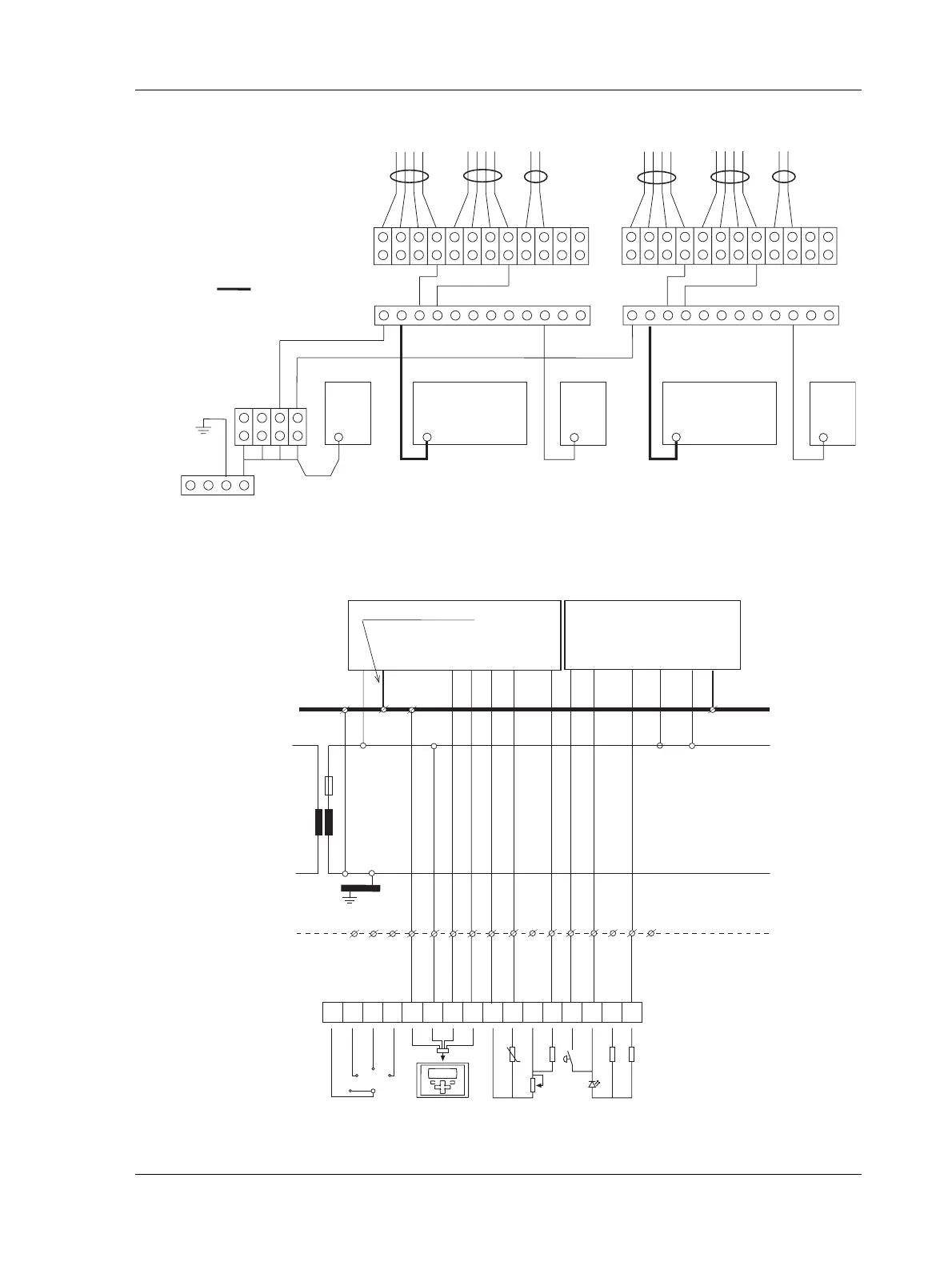
Fig. 4.16: Connections between insulated signal ground rails and the cabinet ground rail
TAC Xenta 2
G0
PU
G0
TAC Xenta 1
G0
PU
G0
TR
G0
min 1.5 mm
2
Cabinet
ground
rail
Incoming cables for TAC Xenta 1 Incoming cables for TAC Xenta 2
Insulated signal ground rail
Insulated signal ground rail
Fig. 4.17: Basic circuit diagram for connecting Wall Module ZS 101–105 to TAC Xenta 400 I/O modules
TAC Xenta 45x
Cabinet
terminals
ZS 101-105
G G0 C2 C1 M B1 B2
F0 F1 F2 F3 G0 G C2 C1 1 2 3 4 5 6 7 8
0
1
2
3
10 kΩ
470 Ω
(24 V AC)
min 1.5 mm
2
, max 2 m
230
VAC
G
G0
N
Insulated
signal
ground rail
Cabinet
ground
rail
TAC Xenta 42x
X1 M K1 KC1 G G0