10 of 16
Wiring the Sensors
Do not apply power to the sensors or the sensor terminals as this will damage either the sensors or the control.
Begin by removing the eight (8) pin plug-in terminal block from the VSMC’s circuit board. To do
this, pull the terminal block directly away from the circuit board.
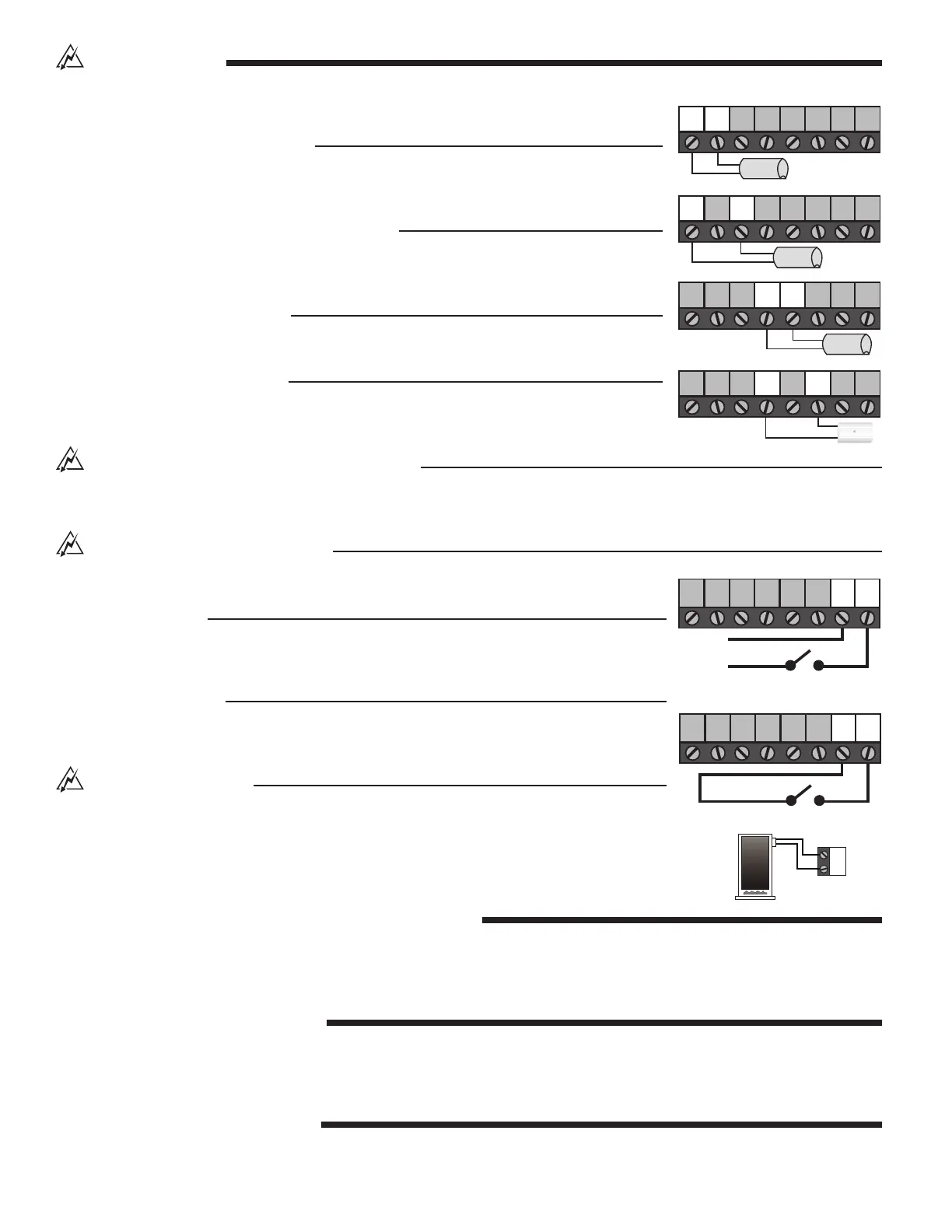
System Supply Sensor (Required)
Connect the two wires from the System Supply Sensor directly to the “Com” and “Sup” termi-
nals of the terminal block. The System Supply Sensor is used to measure the supply tem-
perature being delivered to the system.
System Return Sensor (Delta T Limiting Mode)
Connect the two wires from the System Return Sensor directly to the “Com” and “Sys Ret”
terminals of the terminal block. The System Return Sensor is used to measure the return
temperature from the system.
Heat Source Sensor (Optional)
Connect the two wires from the Heat Source Sensor directly to the “Com” and “Boil” terminals
of the terminal block. The Heat Source Sensor is used to measure the heat source temperature.
Outdoor Sensor (Reset Mode)
Connect the two wires from the Outdoor Sensor directly to the “Com” and “Out” terminals of
the terminal block. The outdoor sensor is used to measure the outdoor air temperature.
Wiring the External Heat Source Pump (Optional)
Using a
3
⁄
16
inch female spade connector, connect the hot side of the heat source pump circuit to the male spade connector labelled
“Pmp” located on the back of the VSMC circuit board. Connect the neutral side of the heat source pump circuit to the neutral (N) side
of the VSMC’s input power supply. When using this option the line cord should be removed and the VSMC hard wired.
Wiring the Heat Demand (Required)
The Heat Demand circuit can be wired using either a powered signal or an unpowered switch
closure.
Powered Demand
If a powered demand is being used, connect the switched side of the 24 V (ac) demand circuit
to the “Heat Dem” terminal of the terminal block. Connect the second side of the
24 V (ac) demand circuit to the “Com” terminal of the terminal block.
Unpowered Demand
If an unpowered demand is being used, connect one side of the demand switch to the “Heat
Dem” terminal of the terminal block. Connect the second side of the demand switch to the
“Com” of the terminal block (relay type thermostat or end switch on zone control).
Wiring the Heat Source
Begin by removing the two (2) pin plug-in terminal block from the VSMC’s circuit board. To do
this, pull the terminal block directly away from the circuit board.
The Heat Source Relay is a switch that is to be used in the heat source circuit. There is no power
available on these terminals from the VSMC. Connect the Heat Source relay in series with the
control circuit of the heat source.
STEP FOUR - RECONNECTING THE TERMINAL BLOCKS
Insert the eight (8) pin plug-in terminal block into the eight (8) pin terminal header on the VSMC circuit board. Press firmly until it snaps
into place.
Insert the two (2) pin plug-in terminal block into the two (2) pin terminal header on the VSMC circuit board. Press firmly until it snaps
into place.
STEP FIVE - MOUNTING THE VSMC
• Begin by pushing all excess wiring back into the X – Pump Block.
• Place the VSMC into the X – Pump Block’s plastic enclosure.
• Insert the screw into the hole located on the face of the VSMC and tighten the screw to fasten the VSMC to the X – Pump Block
Enclosure. Do not overtighten.
STEP SIX - POWERING THE VSMC
Apply power to the VSMC circuit by plugging in the line cord.
Com Heat
Dem
Boil OutSys
Ret
ComCom Sup
Com Heat
Dem
Boil OutSys
Ret
ComCom Sup
Com Heat
Dem
Boil OutSys
Ret
ComCom Sup
Boiler
Com Heat
Dem
Boil OutSys
Ret
ComCom Sup
C
24 V (ac)
R
Switch
Com Heat
Dem
Boil OutSys
Ret
ComCom Sup
Powered Heat Demand
Switch
Com Heat
Dem
Boil OutSys
Ret
ComCom Sup
Unpowered Heat Demand