4 of 16
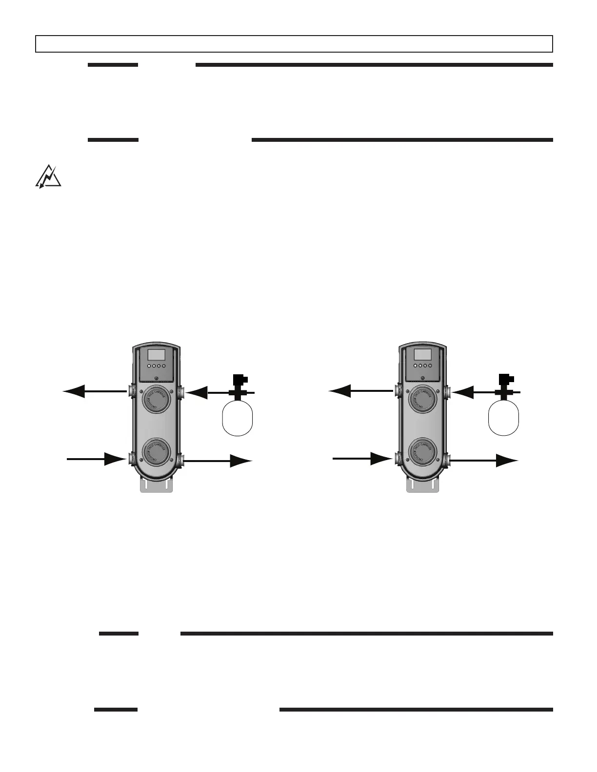
Snow
Return
Supply
Heat Source
Return
Heat Source
Supply
Exp
Tank
Pressure
Relief
Melt
Snow Melt
Variable
Flow
Constant
Flow
Radiant
Return
Radiant
Supply
Heat Source
Return
Heat Source
Supply
Exp
Tank
Pressure
Relief
Variable
Flow
Constant
Flow
When using the X - Pump Block on snow melting systems, it is recommended to switch the system pump motor with the variable
speed pump motor to protect the brazed plate heat exchanger from freezing up.
Follow the instructions for cartridge replacement (page 14) to disassemble the X – Pump.
Unbolt the fixed speed system pump motor (lower) and switch it with the heat source variable speed pump motor (upper).
This now insures constant flow on the heat source side of heat exchanger by the fixed speed pump to minimize the chance of freeze
up. The snow melt system pump is now variable speed and both the System Supply Sensor and System Return Sensor must be
installed and in Setpoint with delta T max mode.
STEP THREE FILLING
1. Fill both system and heat source with tap water – The system must be filled before operating the circulator. The bearings are water
lubricated and should not be allowed to operate dry. Filling the system will result in immediate lubrication of the bearings. It is always
good practice to flush a new system of foreign matter before starting the circulator.
2. Circulator operation – Operate the circulators for 5 minutes immediately after filling system to purge remaining air from the bearing
chamber. This is especially important when installing the circulator during the off-season.
STEP FOUR ELECTRICAL CONNECTIONS
1. Observe all applicable codes when connecting to power supply. The motors are impedance protected, and do not require overload
protection. The pumps cannot run backwards.
STEP ONE MOUNTING
1. Mounting position – The X – Pump Block must be mounted in the vertical position with the Variable Speed Mixing Control (VSMC)
located at the top of the X – Pump Block.
2. Mount the X – Pump Block, using the attached brackets, to a solid surface capable of supporting 23.5 pounds.
3. Using four suitable screws or bolts (
1
⁄
4
”), fasten the X – Pump Block to the selected location. Ensure that at least two of the mounting
screws are attached to a wall stud or similar surface.
STEP TWO PIPING CONNECTIONS
1. Using proper piping practices, connect the supply to the radiant heating system to the Radiant Supply (bottom right hand connec-
tion) as indicated on the plastic cover of the X – Pump Block. Ensure that a proper isolation valve is installed.
2. Using proper piping practices, connect the return from the radiant heating system to the Radiant Return (top right hand connection)
as indicated on the plastic cover of the X – Pump Block. Ensure that a proper isolation valve is installed.
3. Using proper piping practices, connect the supply from the heat source to the Heat Source Supply (bottom left hand connection) as
indicated on the plastic cover of the X – Pump Block. Ensure that a proper isolation valve is installed.
4. Using proper piping practices, connect the return to the heat source to the Heat Source Return (top left hand connection) as
indicated on the plastic cover of the X – Pump Block. Ensure that a proper isolation valve is installed.
5. When using a non-condensing heat source as heat source, connect the Heat Source Supply and Heat Source Return lines of the
X – Pump Block to the heat source loop using standard Primary Secondary piping practices.
Installation of the X – Pump Block
Warning! Must Install a pressure relief valve and expansion tank on secondary side in addition to units
installed on primary side of system. Note! Heat should never be applied to X – Pump Block connections
or damage to housing and/or electronics may result.
Refer to Page 2 for More Piping Diagrams