8 of 16
kept on until the supply water temperature rises
1
/
2
of the differential above the required heat source supply temperature. If the
differential is too wide, there can be large supply water temperature swings; however, if the differential is too narrow, the heat source
short cycles and operates inefficiently. This control automatically calculates the heat source differential in order to achieve an
appropriate balance between temperature swings and heat source efficiency. This also permits the control to adapt to changing
loads and conditions. The VSMC only operates the heat source once the output of the injection circulator exceeds 10% of flow.
HEAT SOURCE ENABLE
When the VSMC “Enables” the heat source, the VSMC opens and closes the heat source contact based on the output of the variable
speed pump. The actual temperature and cycling of the heat source is then determined by other controls or the aquastats on the heat
source itself.
When operating in the heat source enable mode, the heat source contact turns on once the variable speed output exceeds 25%. The
heat source contact shuts off if the output of the variable speed drops below 5% for more than three minutes or if the demand is
removed from the VSMC.
HEAT SOURCE PROTECTION (HEAT SOURCE MINIMUM)
Cool water is often returned to the heat source from low temperature radiant floor heating systems or snow melting systems. This cool
heat source return water may cause the heat source to operate at such a low temperature that the flue gases condensate. Alterna-
tively, when the heat source surfaces are hot due to previous loads such as domestic hot water generation, the large temperature
difference (Delta T) between the heat source and its return water can cause the heat source to become thermally shocked. Proper
protection of the heat source under these circumstances is required.
When a heat source sensor is connected to the control, the VSMC is capable of providing heat source protection. When providing heat
source protection, the VSMC limits the output of the variable speed pump in order to reduce the amount of cool water being returned
to the heat source. This allows the heat source temperature to increase to a point that avoids flue gas condensation.
Heat Source Protection with Heat Source Enable
When the Heat Source Sensor is set to the “Return” setting the control begins to back off the variable speed pump when the heat
source temperature drops below the Heat Source Minimum Setting.
Heat Source Protection with Heat Source Control
When the Heat Source Sensor is set to the “Supply” setting the control begins to back off the variable speed pump when the heat
source temperature drops
1
/
2
of the Differential below the Heat Source Minimum Setting.
Note: If a heat source sensor is not installed, the VSMC cannot provide heat source protection.
CAUTION
Improper installation and operation of this product could result in damage to the equipment and possibly personal injury. It is your
responsibility to ensure that this product is installed in a safe manner according to all of the applicable codes, standards and instruc-
tions. The electronic control contained in this product is not intended as a primary limit control. Removal of the PC Board from its
enclosure can result in damage to the control and possibly even personal injury. Refer to qualified personnel for servicing.
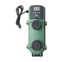
STEP ONE - REMOVING THE VARIABLE SPEED MIXING CONTROL FROM THE X – PUMP BLOCK
• Remove the screw from the front of the control.
• Grasp the front of the control and remove it from the green plastic enclosure surrounding the injection mixing block.
• Wiring to the control is connected to the back of the circuit board using either the indicated spade connectors, molex connectors or
the snap on terminal plugs. These may need to be disconnected to fully remove the control.
Set Up of Variable Speed Mixing Control