Do you have a question about the Tadano Mantis 10010MX and is the answer not in the manual?
Explains the manual's purpose for safe operation and maintenance.
Outlines the structure and content of each section in the manual.
Guides users on how to find information within the manual.
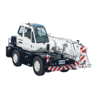
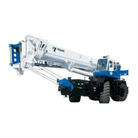
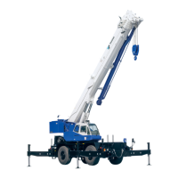
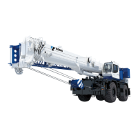
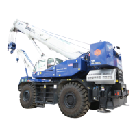
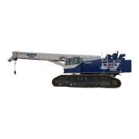
General introduction to the 10010MX crane model.
Details the environmental conditions for crane operation.
Defines directional terms used in crane operations and travel.
Explains how to read and use boom load charts for safe lifting.
Specifies capacity limitations and general conditions for crane operation.
Lists factors that increase the risk of crane tipping.
Provides detailed specifications for the crane and its components.
Describes the standard configuration and recommended parts.
Details the boom specifications, including length and height.
Explains the hydraulic systems for boom extension and elevation.
Describes the boom head components, including sheaves.
Details the function and features of the RCI system.
Explains the function of the anti-two block safety system.
Details the components of the crane's superstructure.
Describes the structural frame of the crane.
Provides specifications for the Cummins diesel engine.
Details the features and layout of the operator's cab.
Describes the gauges, indicators, and accessories in the cab.
Explains the primary control methods using joysticks and pedals.
Details the counterweight specifications and installation.
Describes the main and auxiliary hoist winch specifications.
Outlines the safety protection features of the hydraulic circuits.
Details the crane's electrical system specifications.
Explains the swing mechanism and its components.
Describes the fuel tank and filtration system.
Details the hydraulic system's pumps, reservoir, and filtering.
Describes the crane's undercarriage and track systems.
Details the carbody structure and its function.
Describes the removable side frames and track components.
Explains the travel system, including motors and brakes.
Lists and describes optional equipment available for the crane.
Details optional boom extensions and jibs.
Describes optional hydraulic packages like auger and tool circuits.
Highlights the importance of following all safety precautions.
Defines the meaning of DANGER, WARNING, and CAUTION labels.
Outlines essential safety rules for crane operators and personnel.
Provides general safety instructions for operating the crane.
Specifies the intended use and limitations of the crane.
Explains how to determine and adhere to lifting capacities.
Describes the function and importance of safety devices like RCI.
Lists critical pre-operation checks for safe deployment.
Provides guidelines for proper crane placement on stable ground.
Explains the role of counterweight in crane stability and capacity.
Covers essential safety practices for rigging and signaling.
Illustrates standard hand signals for crane operation communication.
Provides safety instructions for performing lifting operations.
Details critical safety precautions for working near power lines.
Explains procedures for grounding the crane in electrical hazard situations.
Outlines inspection requirements after electrical shock or lightning.
Provides safety guidance for operating in adverse weather conditions.
Highlights safety considerations for working near pipelines.
Offers advice for operating the crane in cold weather conditions.
Provides instructions for safely parking and securing the crane.
Identifies common causes of accidents during crane operation and maintenance.
Lists specific operational errors that can lead to accidents.
Lists maintenance and servicing errors that can cause accidents.
Details hazards related to fire, smoke, and explosion.
Shows the location of warning and instruction decals on the crane.
Shows the location of export-specific warning and instruction decals.
Illustrates the location of decals within the operator's cab.
Briefly introduces the AML system and refers to Appendix A for details.
Identifies the main functional groups of controls in the cab.
Explains the features and operating ranges of the cab display.
Describes the Engine, Hydraulic, and Camera pages of the display.
Details the Service and Valve Adjustment pages for settings.
Provides a reference for understanding the icons shown on the display.
Details the function and operation of the switch panel controls.
Explains the meaning and function of the engine status LEDs.
Describes the correct procedure for starting the engine.
Explains the ignition switch for starting and stopping the engine.
Describes the operation of the foot throttle pedal for engine speed control.
Explains how to use the left joystick for swing control.
Describes the function of the swing brake pedal.
Explains the operation of the swing park brake engagement switch.
Explains how to use the left joystick for boom telescope control.
Details the operation of the auxiliary winch using the left joystick.
Explains how to use the right joystick for main winch and boom hoist control.
Describes the controls for crane travel operations.
Details controls for optional equipment like tool circuits and augers.
Covers miscellaneous controls such as fan, heater, and AC.
Explains the emergency system for operating functions during failures.
Describes the function of the battery cutoff switch.
Provides general operating procedures and checks.
Lists essential checks to perform before starting the engine.
Details the procedure for starting the engine electrically.
Offers advice for operating the crane in cold weather conditions.
Explains the operation of the main and auxiliary winches.
Details the controls for boom hoist, telescope, and stability.
Explains the operation of the track forward/reverse and extend/retract controls.
Describes how to operate the optional auger attachment.
Illustrates correct reeving patterns for efficient operation.
Outlines procedures for preparing the crane for transport.
Details the procedure for installing and removing counterweight.
Provides instructions for removing and installing the jib and extension.
Explains the process for erecting and rigging the boom extension and jib.
Emphasizes the importance of timely lubrication and maintenance.
Defines maintenance schedules based on operating hours or time.
Covers general inspection, servicing, and maintenance of the engine.
Details procedures for draining condensation and cleaning the fuel strainer.
Explains inspection and maintenance of the engine cooling system.
Provides instructions for cleaning the radiator and cooler fins.
Details the removal, installation, and maintenance of the air cleaner.
States that the exhaust system requires no particular service.
Covers maintenance procedures for the hydraulic system.
Lists specified speed set-points for hydraulic functions.
Explains how to check and set hydraulic system pressures.
Covers maintenance of batteries, starter, and circuit breakers.
Specifies that RCI must be serviced by qualified personnel only.
Details maintenance procedures for the swing mechanism.
Covers maintenance procedures for the main and auxiliary winches.
Explains the function and testing of the A2B safety system.
Details maintenance for track drive reducers, tension, and undercarriage.
Explains the setting and function of the last wrap indicator.
Covers inspection, cleaning, lubrication, and replacement of winch rope.
Provides maintenance guidelines for cabin components and systems.
Specifies lubrication points for the boom, cylinders, and hook block.
Provides tables for lubrication types, capacities, and filter specifications.
General overview of the Load Moment Indicator system.
Identifies the main components of the LMI system: display and controls.
Describes the information displayed on the LMI panel.
Explains the meaning of the LED indicators on the LMI system.
Procedure for registering crane configuration and checking LMI functions.
Steps to register the crane's counterweight configuration in the LMI.
Procedure to register the track or carbody jack configuration in the LMI.
Steps to register the boom configuration, including jib and extensions.
Procedure to register the number of parts of line used for the lift.
Final verification steps for the AML indicator configuration.
Explains how to interpret and respond to LMI alarms and errors.
Lists and explains stop alarm codes and their remedies.
Lists and explains warning alarm codes and their remedies.
Describes additional functions of the LMI system.
Explains the function and setup of the work range alarm.
Procedure for registering alarm limits for boom angle, height, and radius.
Describes how to cancel registered work range alarms.
Explains how to use the TARE function to zero the load display.
Details how to adjust display settings like panel contrast.
Step-by-step guide for adjusting the display panel contrast.
Provides actions to take for LMI system errors.
Provides instructions for setting up the Drum Rotation Indicator.
Details the wiring connections for the drum rotation and LLI indicators.
Provides instructions for programming the Last Layer Indicator.
| Brand | Tadano |
|---|---|
| Model | Mantis 10010MX |
| Category | Construction Equipment |
| Language | English |