TA-05/C
ETA-05C.PMD PT
Misprints and technical changes reserved
TAE Antriebstechnik
Instrucon & Operang Manual
5
Copyright © by TAE Antriebstechnik
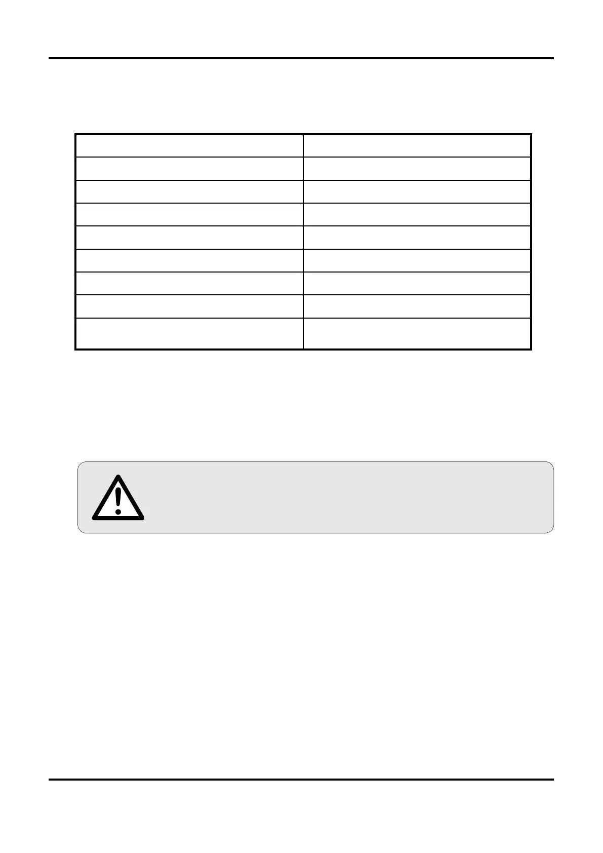
2. Technical data
2.1 Equipment
Semi-controled single phase bridge
Acceleration/Deceleration integrator
Inner loop current regulator
Torque control
The electronic circuit is galvanically seperated from the line supply
on units with a current-transformer for armature-current detection
and tachometer control. If armature-voltage control is used the
electronic circuit is at line potential.
3. Connection of unit (refer to Connection diagram TA-05 C chapter 8.)
2dz - 6dz Line supply refer to Type-Marking - 230V AC 50/60Hz
2dz = Phase (L1)
6dz = MP (N, neutral)
10dz - 14dz Armature connection 10dz = A+
14dz = A-
18dz - 16dz Field connection 18dz = F+
16dz = F-
28d - 26d Drive release by relay contact.
Jumper III "internal" refer to layout chapter 9.
26d - 12d Drive release by SPS (free potential).
Jumper III "external" refer to layout chapter 9.
Dimensions refer to drawing chapter 10
Line Voltage 230VAC - 50/60Hz
Power 0,7 kW
Armature Voltage 180V
Armature Current max. 6 Ampere e.
Field Voltage 210V
Field Current max. 0,5 A
Ambient temperature 0-40°C
Speed Accuracy
with armature feedback 3%
with tachometer feedback 1%