XT-1/XT Mini Manual 13-111 05, 2015-08-14
Page 19 of 32
DIP Switches
Two 8-position DIP switches are available for interface and software configuration.
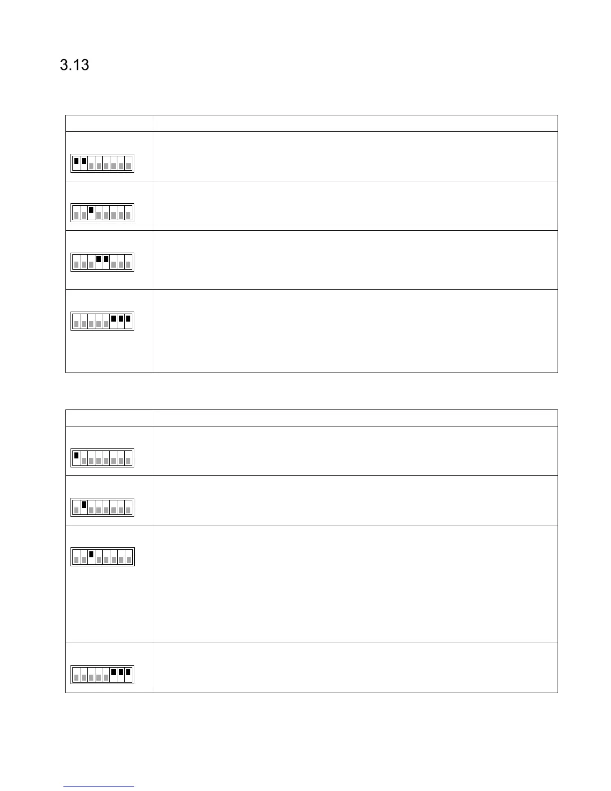
3.13.1 Interface Configuration DIP Switch (S301)
S301:1 ON = TX+ connected to RX+
S301:2 ON = TX– connected to RX–
3
S301:3 ON = 120 Ω termination between RX+ and RX-.
Termination should be activated at each end of an RS485 chain.
4-5
S301:4 ON = 620 Ω pull-up from RX+ to 5 V
S301:5 ON = 620 Ω pull-down from RX- to 0 V
Bias should be activated at one node in an RS485 chain.
6-8
S301:6 ON = 1 kΩ pull-up from D0/CLK to 5 V
S301:7 ON = 1 kΩ pull-up from D1/DATA to 5 V
S301:8 ON = 1 kΩ pull-up from CL/LOAD to 5 V
Pull-ups should be activated when the reader is connected to an access control
system without built-in pull-ups.
Table 13 Interface Configuration DIP Switch (S301)
3.13.2 Software Configuration DIP Switch (S101)
S101:1 is used for firmware upgrade. See section 4.4 for more information.
2
S101:2 is used to restore the reader to factory default settings.
See section 4.5 for more information.
3
S101:3 forces the reader to use the following IP settings:
IP address: 169.254.1.1
Netmask: 255.255.0.0
A Windows PC that is directly connected to a reader is normally automatically
assigned an IP address in the 169.254.x.x range. This means that it is possible to
connect to a reader without changing IP settings on the PC. It may be necessary to
run "ipconfig /release" if the PC has received IP settings over DHCP.
6-8
S101:6-8 are used for easy configuration of Wiegand/Magstripe, OSDP, and other
settings. See sections 5.1.1 and 5.2.1 for more information.
Table 14 Software Configuration DIP Switch (S101)
1 8
ON
S301
1 8
ON
S301
1 8
ON
S301
1 8
ON
S301
1 8
ON
S101
1 8
ON
S101
1 8
ON
S101
1 8
ON
S101