XT-1/XT Mini Manual 13-111 05, 2015-08-14
Page 9 of 32
Cable Connections
2.4.1 XT-1
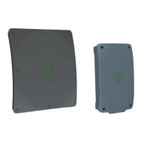
In XT-1, cables should primarily be connected through the central M20 cable gland. This cable gland can
be used with one cable (Ø 6-12 mm) or two cables (Ø 2-6 mm) using the supplied insert. As an alternative,
one or more of the four M16 blind plugs can be replaced with cable glands. Use shielded flexible cables
with stranded wire. Ground the reader chassis using the grounding screw.
Figure 8 XT-1 with open lid (left), cable gland with insert for two cables (right)
2.4.2 XT Mini
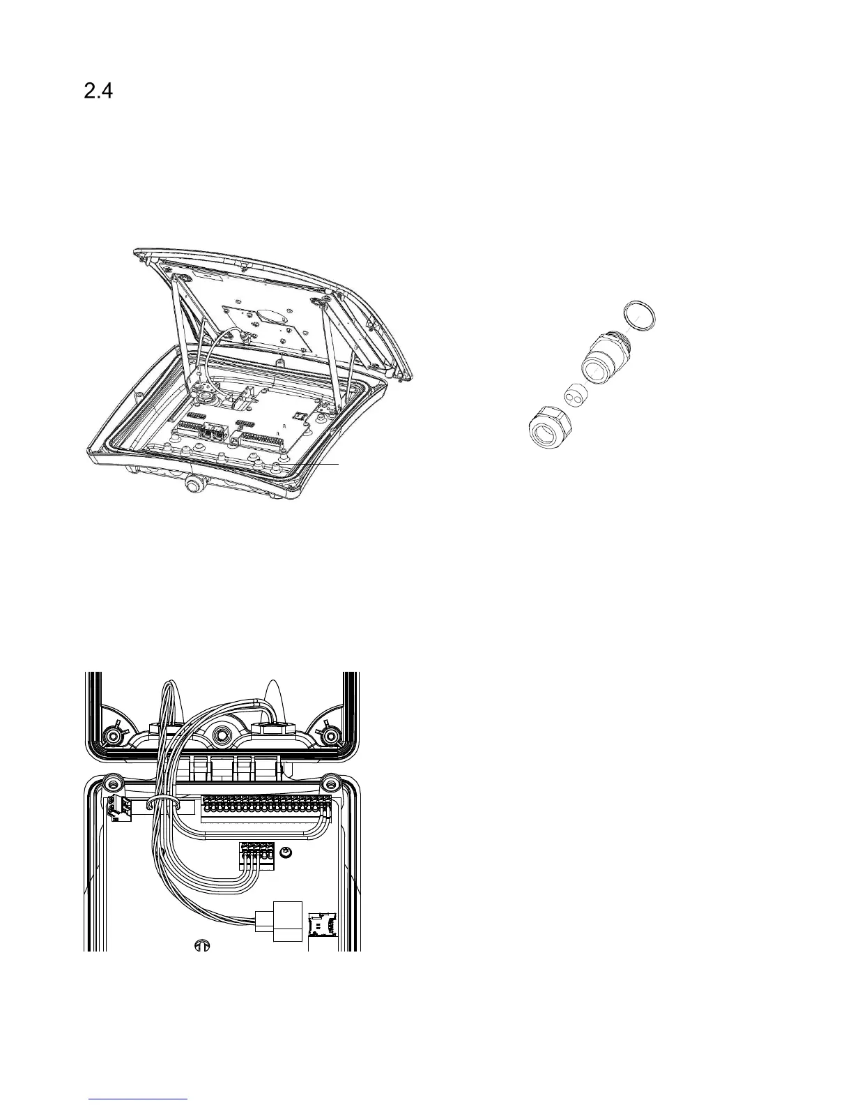
In XT Mini, cables should be connected through the two M16 cable glands. A cable tie should be used to
guide the wires when the lid is closed. Make sure to use cables with flexible wires. It is recommended to
use the left cable gland for Ethernet connections and the right cable gland for other connections. An
example with power, Ethernet and RS485 connections is shown in Figure 9.
Figure 9 XT Mini with power, Ethernet and RS485 connections
Grounding screw