M2000-00
T2000-A03/-A04/-A16 Remote Loom Kits
8.16.5
Copyright TEL 31/12/97
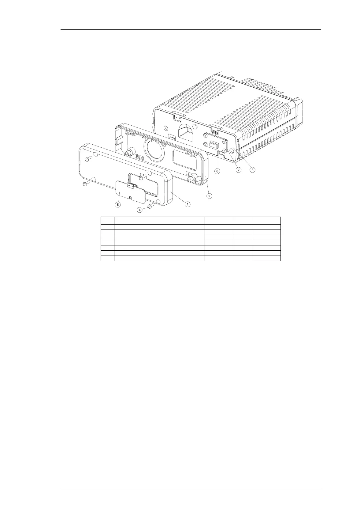
Mount the dummy head front panel (1) onto the adaptor plate (2), using the 4 No
4x3/8 Plastite screws (4) provided.
Mount the dummy front panel assembly onto the chassis.
Figure 8.16.4 Dummy Front Panel Assembly
6 Reposition the bottom cover of the radio and the microprocessor shield and
replace the microprocessor shield retaining screws, tightening them to a torque of
12in.lb (1.4Nm).
Refit the logic PCB, any options PCBs that were fitted and the top cover. Tighten
the top cover to a torque of 15in.lb (1.8Nm).
Refit the remoting connector cover, pushing the slot in the cover onto the remote
loom cable.
7 Mount the remote mounting bracket in the desired position (this must be on a flat
surface), using the 2 No 6x3/4 self-tapping screws.
Place the control head in the bracket, positioned for a good viewing angle, and
secure in place with the 2 thumbscrews.
Item Description IPN Quantity Torque (in.lb)
1 DUMMY FRONT PANEL 316-06433-XX 1
2 ADAPTOR PLATE 301-00001-XX 1
3 MAIN CHASSIS ASSEMBLY 1
4 NO 4X3/8 SCREW (DUMMY FRONT PANEL SCREWS) 349-00010-22 4 8 (0.9Nm)
5 REMOTING CONNECTOR COVER 316-85125-XX 1
6 8 WAY EMC FILTER PCB SOCKET 240-04020-50 1
7 EMC FILTER PCB 220-01383-XX 1
 Loading...