Do you have a question about the Tait T2000 SERIES II and is the answer not in the manual?
Grants non-exclusive rights to use Tait software programs on a single machine, with specific usage permissions.
States that ownership of the software remains with Tait, regardless of media possession by the licensee.
Defines licence duration and conditions for termination by either party, including automatic termination for non-compliance.
Provides a limited warranty for diskettes against material/workmanship defects for 90 days, with no warranty on software performance.
Limits Tait's liability for consequential damages arising from software use, with replacement or termination as remedies.
Governs the agreement under New Zealand law, with disputes to be settled by New Zealand courts or Tait's chosen jurisdiction.
Plan the radio and accessory mounting locations within the vehicle for efficient installation.
Ensure radio placement avoids endangering occupants and allows for safe operation with seat belts.
Remove the radio unit from its mounting cradle using the provided plastic key tool.
Secure the metal cradle cover to the chosen mounting surface using appropriate screws or bolts.
Reattach the plastic side mouldings and remaining metal cover to the cradle assembly.
Connect an external speaker, disabling the internal speaker if necessary via the power connector link.
Safely connect the power cable by disconnecting the battery, routing wires, and installing fuses.
Wire external functions like horn or emergency switch to the power connector and vehicle wiring.
Install the remote control head separately, routing its connecting cable with care to prevent damage.
Mount the microphone clip, ensuring it is earthed for hookswitch functions and positioned safely.
This document is an installation guide for the Tait T2000 Series II radio, providing comprehensive instructions for setting up the device and its accessories in a vehicle. The guide emphasizes safe and efficient installation practices, ensuring optimal performance and user safety.
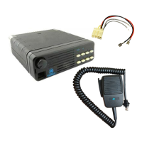
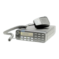
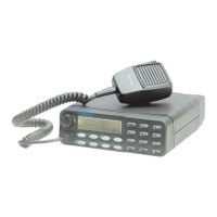
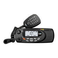
The Tait T2000 Series II radio is designed for mobile radio communications, offering robust and reliable performance in various operational environments. It is intended for use in vehicles, providing communication capabilities for professional and commercial applications. The radio unit itself is a compact device, typically mounted in a cradle within the vehicle. Depending on the specific model (T2020II, T2040II, T2050II), some versions feature alphanumeric keypads and a control head that can be separated from the main radio chassis, allowing for remote mounting. This flexibility enables the radio to be installed in a discrete location, such as the rear luggage compartment, while the control head is positioned conveniently for the vehicle's occupants.
The T2000 Series II radio is designed for straightforward operation once installed. Key usage features revolve around its communication capabilities, including transmitting and receiving radio signals. The control head, when present, provides the user interface for channel selection, volume control, and other operational settings. The microphone, an essential accessory, allows for voice communication. The radio can be configured to interact with vehicle systems, such as the horn, for specific functions like emergency alerts or call signaling, depending on the interface unit's configuration. The economizer function, if enabled, can be controlled by the vehicle's ignition, ensuring the radio operates only when the vehicle is switched on, thereby conserving power.
The remote control head option significantly enhances usability by allowing the main radio unit to be hidden from view, while the control panel remains accessible to the operator. This is particularly useful in environments where space is limited or where a discreet installation is preferred. The design ensures that the control head can be positioned for optimal viewing and operation, even when seat belts are worn, prioritizing occupant safety and convenience.
The installation process is detailed, starting with planning to ensure proper placement of the antenna, radio, and accessories. This planning phase is crucial for preventing interference with vehicle electronic systems, such as ignition and anti-skid devices, and for ensuring adequate airflow around the radio for cooling.
The radio unit is secured within a cradle, which must first be disassembled for mounting. The cradle consists of a metal cover and plastic side mouldings. Disassembly involves sliding a plastic key into a slot on the radio unit to release it from the cradle, and then carefully detaching the plastic mouldings from the metal cover using a screwdriver.
Mounting the cradle involves marking drilling locations using the metal cradle cover as a template, indenting these positions with a centre punch, and drilling appropriate holes (4mm for self-tapping screws or 6mm for nuts and bolts). It's important to ensure that drilling does not damage existing wiring and that the cradle is secured without distortion. Additional holes may be required for cables, which should be fitted with grommets or bushings to prevent chafing. Reassembly of the cradle involves clipping the plastic side mouldings back onto the metal cover and securing the remaining metal cover.
Antenna installation is critical for radio performance. The guide recommends specific mounting positions for ground-plane dependent antennas (e.g., on the vehicle roof or trunk lid) to ensure optimal signal transmission and reception. For ground-independent antennas, the manufacturer's guidelines should be followed. A key safety consideration is mounting the antenna such that no part of the human body is normally within 20cm of it for extended periods while the radio is on, unless there is an intervening metal screen. The coaxial cable connecting the antenna to the radio must be of good quality (50 ohm, such as RG58 or UR76) and terminated with the supplied BNC crimp plug using a specific crimping procedure to ensure a secure and efficient connection.
Wiring instructions cover the external speaker, power cable, and external wires for features like horn, hush, or emergency functions. For models with internal speakers, an external speaker can be added, and the internal speaker can be disabled by cutting a link on the power connector. Models without internal speakers require an external speaker. The power cable connection requires disconnecting the vehicle's battery for safety, routing the leads, and inserting in-line crimp fuse holders as close to the battery as possible. Both positive and negative wires must be terminated at the battery, with extreme caution to prevent chafing against metal parts. The radio operates on a nominal 12V negative earth supply (10.8V to 16.0V) and requires up to 8A. For 24V vehicle systems, a 24/12V converter (e.g., Tait T2007) is essential to protect the radio from excessive voltages. The economizer function can be wired to the vehicle's ignition for automatic power control.
The remote control head option, if applicable, involves routing a cable from the control head to the radio chassis. If the cable needs to pass through a bulkhead, it can be unplugged from the control head by unscrewing the rear cover, disconnecting the red connector from the circuit board, routing the cable with grommets, and then reassembling. The control head bracket is then mounted on a flat surface, and the control head is secured in place for optimal viewing.
The microphone clip installation requires earthing to the negative supply line for hookswitch control functions (monitoring, scanning, call termination). It must be mounted in a position where the PTT (Push-To-Talk) key cannot be accidentally activated or jammed.
Installation checks are performed after all components are installed. These include plugging in the microphone, inserting fuses, switching on the radio to confirm operation, and measuring forward and reflected power levels using an in-line power meter. Reflected power should be less than 1W for 25W forward power; if not, the antenna installation needs to be re-checked. Finally, a test call is made to another party to confirm communication functionality.
The manual emphasizes that Tait Electronics makes every effort to ensure accuracy but reserves the right to update the radio and/or manual without notice, indicating a commitment to continuous improvement and product evolution.
| Operating Temperature | -30°C to +60°C |
|---|---|
| IP Rating | IP54 |
| Frequency Range | VHF: 136-174 MHz, UHF: 400-470 MHz |
| Modulation | FM |
| Channel Spacing | 12.5 kHz, 25 kHz |
| Operating Voltage | 7.4 V DC |