C2.10
T856/857 Circuit Operation
M850-00
31/09/98 Copyright TEL
2.6 Power Supply & Regulator Circuits
(Refer to the regulators circuit diagram (sheet 6) in Section 6.2 or 6.3.)
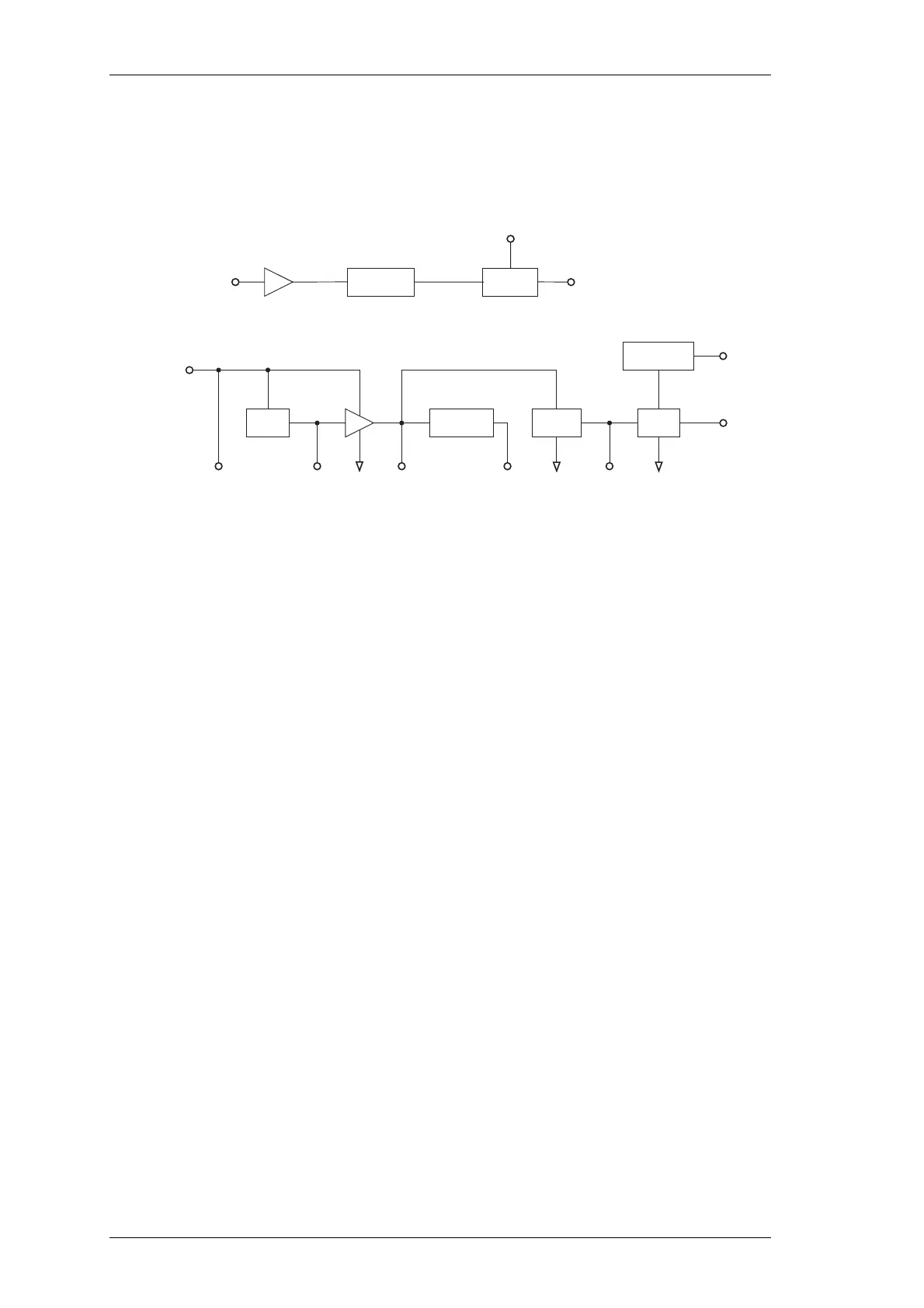
Figure 2.7 T856/857 Power Supply & Regulators Block Diagram
The T856 and T857 are designed to operate from a 10.8-16V DC supply (13.8V nominal).
A 5.3V regulator (IC630) runs directly from the 13.8V rail, driving much of the synthe-
siser circuitry. It is also used as the reference for a DC amplifier (IC640, Q630, Q620)
which provides a medium current capability 9V supply. The T856 has a regulator
(IC370) which produces 9V for use in the exciter and audio circuits.
A switching power supply (Q660, Q670) runs from the 9V supply and provides a low
current capability +20V supply. This is used to drive the synthesiser loop filter (IC750),
giving a VCO control voltage range of up to 20V.
Ultimate control of the transmitter is via the Tx-Reg. supply, switched from 9V by Q610.
This is enabled via the Tx-Enable signal from the audio processor, and microprocessor.
LVI
5V
Reg
DC
Amp
Switching
PS
5V Dig
Reg
Power
Switch
13.8V
Nom.
5V 5V Dig9V 20V
13.8V Nom.
From Rear
D-Range
Tx Enable
Buffer
Tx Reg.
+9V
µP
Watchdog
Timer
Micro-
controller
µP
Reset
 Loading...


