15
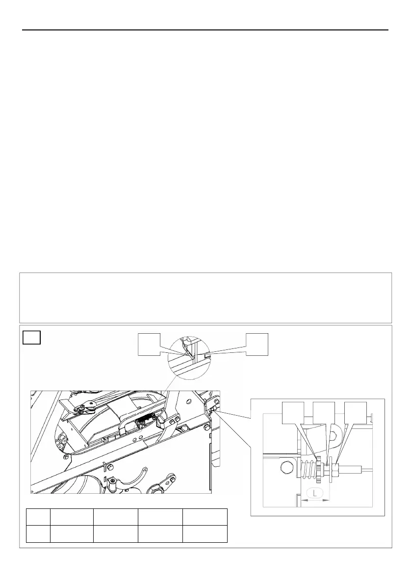
4.7. SETTING THE WINCH BRAKE POWER (Figure: 9)
The brake band is s factory set to the brake power which is 25 % higher than the nominal
pulling power of the winch. The brake power changes due to the wear of the brake band lining
and has to be readjusted periodically. Properly adjusted brake band prevents the load from
sliding backwards when the brake handle is the right position and allows pulling the wire rope
out of the winch, when the brake handle is in the »permanent brake release« position.
Set the brake power by screwing or unscrewing the drawn cup 42, to reach the distance L.
(Distance »L« is only an orientation point for approximate setting of brake power. Exact set-
ting can only be achieved by using a measuring instrument).
By screwing the drawn cup 42 from its starting position, you increase the brake power, and
vice versa.
Using spanner No 19 screw the counter nut 43 to prevent unscrewing of the drawn cup 42.
Setting the initial position:
Remove the triangular shield 3 (Fig.: 5) by unscrewing the screw 2 (Fig.: 5).
Push the clutch handle 3 to the left and release the clutch handle 10 again. The clutch
handle is now in the right position.
Check if the groove on the lower bar of the blocking mechanism M is aligned with the outer
edge of the chassis 45. If this is not the case, adjust the position of the groove by screwing
or unscrewing the drawn cup 42 and counter nut 43. Screw the counter nut tightly
afterwards.
WARNING:
If the brake handle 20 has been previously in the left “permanent brake release” position, the
brake handle 20 may suddenly switch back to the right position, when you move the clutch
handle 10.
9
41 42 43
45 M
EGV 45A EGV 55A
L
52 mm 52 mm
EGV 65A
52 mm
EGV 85A
50 mm
 Loading...