System Installation
Warning: Installation or service of this water heater
requires licensed person or qualified professional
service technician in water heater installation.
Operation creates carbon monoxide gas and flue
gases, which can cause serious injury or death.
Improper installation and/or operation, or
installation by an unqualified person, will void
warranty.
Indoor Clearances
Piping side 6”
Front (Maintenance
space)
Suggested 24”
Min. 4”
Back of heater 1”
Non piping side 0.5”
Top of heater 12”
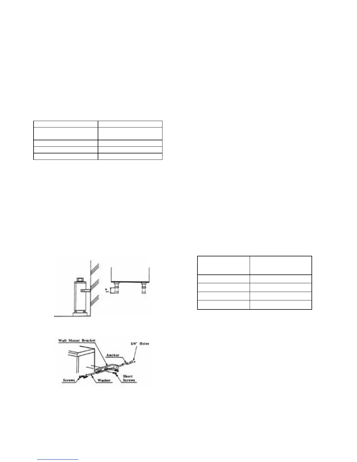
Wall Hanging Installation
For a wall mount installation, use TK-BK01 brackets to
securely attach the T-KD20 to the wall.
Locate the heater as desired, but follow all applicable
local codes, as well as the indoor or outdoor clearances
that apply to the installation.
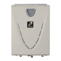
Standing Installation
If the unit is to be installed standing on a surface, adjust
the legs so that the unit stands securely and is level
(legs can be adjusted up to 1”).
Use the included L brackets to connect the unit to a wall
to ensure that it does not fall over. These brackets will
secure between the back of the unit and wall surface.
Combustion Air and Ventilation
Follow all local codes, or in the absence of local codes,
follow the codes for Installation of Gas Burning
Appliances; National Fuel Gas Code ANSI Z221.23 in
USA or CAN/CGA B149.1 or .2 in Canada.
Exhaust Venting
WARNING: The T-KD20 must be connected to a
Category III gas vent for discharge pipe in order to
direct the dangerous exhaust byproducts to the
outdoors.
Connect the 4” Category III vent pipe to the
minimum 2” round collar on through the outside
wall.
This water heater must be vented in accordance with
the section on venting of equipment in the latest edition
of the National Fuel Gas Code.
This is a Category III appliance, and must be vented
accordingly. The following are UL listed or CSA
certified manufacturers: ProTech Systems FasNSeal, Z-
Flex Inc. Z-Vent II and Heat-Fab Inc. Saf-T Vent. This
unit requires 4” vent pipe. Connect the vent pipe to the
unit so that it is sealed airtight. Follow the vent pipe
manufacturer’s instructions when installing the vent pipe.
Do not common vent this appliance with any other
vented appliance.
The venting system must not exceed a length of 25 ft.
minus 5 ft. for every elbow. Do not use more than 3
elbows.
No. of Elbows Max. Vertical or
Horizontal Length
0 25 ft.
1 20 ft.
2 15 ft.
3 10 ft.
If the horizontal vent run exceeds 5 ft., the following
criteria must be observed:
• There must be a 1 ft. vertical run off the top of
the heater before the horizontal run begins.
• The horizontal run must be supported at 3’
intervals.
• The vent run should be pitched up towards the
termination at ¼” per foot.
The unit should be vented out to directly through a wall.
If the unit will be vented through a wall, use Takagi USA
Inc. optional part, the TK-TV05 vent terminator, or an
equal vent terminator that approved by UL or CSA.
Locate the vent terminator according to ANSI
Z223.1/NFPA 54 and applicable local codes.

 Loading...