Do you have a question about the TANDBERG TR-1010 and is the answer not in the manual?
Instructions for removing the unit's cabinet panels.
Procedures for accessing and servicing the FM-IF board.
Steps to access the output power transistors for servicing.
Guide for removing the power amplifier board.
How to detach the front panel for maintenance.
Information on the dial cord drive mechanism.
Maintenance and disassembly of Petrick interlocked switches.
Maintenance and disassembly of Petrick independent switches.
Maintenance and disassembly of Schadow interlocked switches.
Maintenance and disassembly of Schadow independent switches.
List of transistors with part numbers and alternatives.
Listing of diodes, rectifiers, and fuses with part numbers.
Details of potentiometers with part numbers and values.
Mechanical components required for the microphone amplifier.
List of parts for the modified rear panel.
Detailed list of mechanical parts for the front assembly.
Listing of speaker selector and associated mechanical parts.
Test points for adjusting the stereo decoder circuit.
Test points for aligning the FM tuner section.
Steps for aligning the FM oscillator circuit.
Alignment of the aerial circuit for the FM section.
Procedure for aligning the FM Intermediate Frequency section.
Steps to align the discriminator circuit.
Adjusting the tuning meter and AFC sensitivity.
Steps for aligning the AM Intermediate Frequency section.
Alignment procedures for the AM antenna circuit.
Adjusting the DC center voltage of the audio output.
Measuring and adjusting the amplifier's quiescent current.
Calibrating the power output meter.
Explanation of the thermal protection mechanism.
Detailed technical data for the FM receiver section.
Detailed technical data for the AM receiver section.
Technical data for the audio output and controls.
Schematic showing the microphone amplifier circuit.
Necessary circuit board modifications for the mic amp.
Details on component changes to reduce distortion and hum.
Explanation of new components added for stability and feature enhancement.
Step-by-step guide for aligning the stereo decoder.
Procedure to adjust the 19 kHz oscillator frequency.
Setting the level for stereo indicator activation.
Minimizing signal leakage between stereo channels.
Tuning the 19 kHz filter coils for optimal signal.
Listing of resistors R201 through R320 with values and part numbers.
Listing of resistors R321 through R448 with values and part numbers.
Listing of resistors R449 through R839 with values and part numbers.
Listing of capacitors with values and part numbers.
Listing of capacitors C402 through C410 with values and part numbers.
Listing of capacitors C485 through C542 with values and part numbers.
Capacitors used in the type I stereo decoder circuit.
Capacitors used in the type II stereo decoder circuit.
Resistors for the type I stereo decoder circuit.
Resistors for the type II stereo decoder circuit.
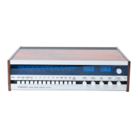
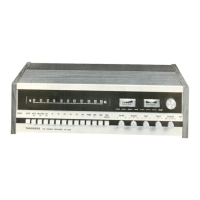
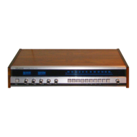
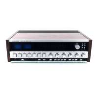
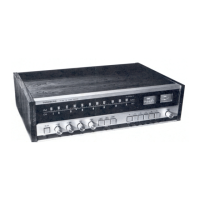
| Brand | TANDBERG |
|---|---|
| Model | TR-1010 |
| Category | Stereo Receiver |
| Language | English |