Do you have a question about the Target PRO 65 III DIESEL and is the answer not in the manual?
Explains symbols for general safety, warnings, prohibitions, and mandatory actions.
Details symbols for required PPE like eye, head, hearing protection, safety shoes, and clothing.
Covers symbols for operational states, controls, hazards, and maintenance indicators like oil pressure, water supply, and engine status.
Identifies decals for the instrument panel and depth indicator, including part numbers.
Locates decals providing operating instructions and critical safety warnings on the saw.
Details decals for battery, lubrication points, guards, and other machine components.
Lists essential actions operators must take, including reading the manual, using PPE, and proper machine handling.
Details actions operators must avoid, such as operating without guards, using damaged parts, or cutting improperly.
Provides a detailed list of parts and quantities corresponding to the Diagram 1 wiring schematic.
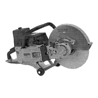
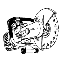
Details blade assembly and guard components shown in Figure 2.
Details water valve, lifting bail, and guide components shown in Figure 3.
Identifies and describes belt, pulley, and sprocket components shown in Figure 4.
Outlines essential checks before starting the machine, including cold checks and initial operation checks.
Provides a schedule for maintenance tasks based on operating hours, including daily, 50, 100, 250, 500 hour, and yearly intervals.
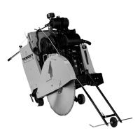
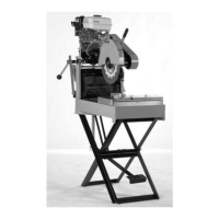
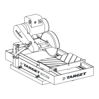
Explains the intended use for wet sawing concrete and asphalt with diamond blades.
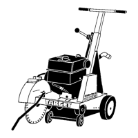
Details procedures for moving the saw with the engine off and with the engine on, including safety precautions.
Procedures for safely starting the engine and saw, including water supply and control lever usage.
Explains how to use the blade depth indicator and set the blade depth stop for consistent cuts.
Instructions for normal and emergency stopping procedures, including engine cool-down.
Troubleshooting guide for engine stops, blade stalls, and saws lowering too fast.
Details how to adjust the rear axle for straight line cutting accuracy.
Covers basic cleaning and daily lubrication points, and engine oil requirements.
Outlines lubrication requirements for 100, 250, and 500-hour intervals, plus transmission and hydraulic systems.
Instructions for checking and replacing the air filter and drive chain service.
Details replacement intervals for fuel filters.
Explains belt tensioning procedures using a Goodyear Tension Rite™ gauge.
Step-by-step guide for tensioning V-belts on the Pro 65 Diesel model.
Procedure for replacing V-belts in sets on the Pro 65 Diesel model.
Instructions for aligning sprockets on the Pro 65 Diesel model after removal or replacement.
Information on selecting and using blade guard conversion kits for different blade sizes.
Details the weight kit and lists available accessories and kits with part numbers.
Explains the use of metric and English hardware systems on the saws.
Information regarding professional repair services for the equipment.
Guidance on how to order spare parts, including necessary machine data and part numbers.
Lists components and their part numbers for the Diagram 4 wiring schematic of the PRO 35 III Electric.
Instructions for configuring the current transformer wiring for different motor connections.
Important notice regarding end-user responsibility for electrical service compliance.