Do you have a question about the Target MC18 and is the answer not in the manual?
Symbols indicating mandatory use of eye, head, breathing, and safety footwear protection.
Symbols for ventilation, prohibited actions, and mandatory safety practices.
Symbols for machinery hazards, exhaust gas dangers, and keeping clear of moving parts.
Symbols for flammable areas, ventilated areas, noise levels, and clean work areas.
Symbols related to fuel type and checking oil levels for maintenance.
Warning about potential hearing damage from noise exposure during operation.
Symbols related to authorized repairs and engine/blade shaft speed specifications.
Identification and location of TARGET decals on the machine's frame and guards.
Decal indicating depth of cut and corresponding blade sizes.
Decals warning about hot mufflers and the importance of the operator's manual.
Decal reminding users to grease bearings daily.
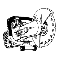
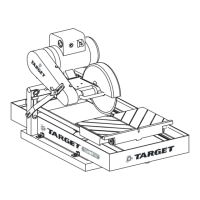
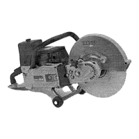
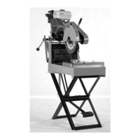
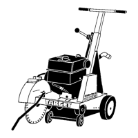
Details on power sources (Gas, Pneumatic, Electric) and model specifications.
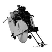
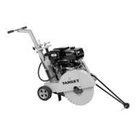
Key features common to all saws and overall machine dimensions.
Key instructions: read manual, keep guards, wear protection, keep clear of moving parts.
Prohibitions: Do not operate without guards, touch moving blades, or use damaged parts.
Avoid enclosed areas, flammable materials, and operating under the influence.
Prohibits operation with removed guards or blade exposure exceeding 180 degrees.
Avoid laying cords near water, towing the machine, or using unauthorized motors.
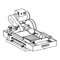
Identification of water valve, stop switch, and depth control hand wheel.
Identification of blade shaft nut, diamond blade, and blade guard parts.
Steps to perform before starting the machine, including cold checks and hourly checks.
Daily and 50-hour service tasks for optimal machine performance.
Information on saw applications, recommended tools, and cutting depth specifications.
Instructions for attaching the handle and checking engine oil levels.
Crucial safety warnings regarding blade guards and water flow requirements.
Ensuring safe working conditions, checking fuel, and engine oil levels.
Step-by-step guide for safely installing the diamond blade onto the saw.
Instructions for starting gasoline, air, and electric motors, including safety stops.
Guidelines for electrical connections, power cords, and unattended operation.
Instructions for moving the saw and initiating the cutting process.
Tips on water supply, avoiding excessive pressure, and handling stalls.
Steps for stopping the saw safely for both screw feed and E-Z tilt versions.
Daily lubrication, 50-hour checks, and V-belt maintenance guidelines.
Information on special flanges, water tanks, and tie-down brackets with safety notes.
Importance of governor settings and risks of blade overspeeding.
Table listing RPMs for different models under no-load conditions.
Guidance on obtaining repairs and ordering spare parts, including model/serial number.
Exploded view showing numbered parts of the frame and axle assembly.
List of main parts including Frame Weldment, Axles, and Wheels.
List of screws, nuts, locknuts, springs, and handle parts.
Exploded view illustrating the numbered parts of the screw feed depth control system.
List of parts for the screw feed mechanism, including nuts, screws, and brackets.
Parts related to the hand wheel, handle, and adjustment screw.
Exploded view showing numbered parts for the lock bar depth control system.
List of parts for the lock bar, lever, stud, and adjustment.
Parts related to the depth pointer, switch bracket, and associated fasteners.
Exploded view showing numbered parts for the pointer and belt guard assembly.
List of parts for the pointer assembly, including bars, wheel, and rope.
Parts for the belt guard, hinge block, and associated fasteners.
Exploded view showing numbered parts for guards and water supply system.
List of parts for the belt guard and the main water valve assembly.
Parts for the water hose, adapters, filters, and water manifold.
Exploded view showing numbered parts of the blade guard assembly.
List of front and rear guard weldments and associated hinge parts.
Parts for the water tube, clamp, plug, gasket, and manifold.
Exploded view showing numbered parts of the engine and bladeshaft assembly.
List of parts for the bladeshaft, including collars, pins, and bearings.
Parts for the engine, pulleys, adapters, and V-belts.
Exploded view showing numbered parts of the electric motor and drive system.
List of parts for the motor, drive pulleys, and V-belts.
Parts for motor adapters, mounting hardware, and washers.
Exploded view showing numbered parts of the air motor and associated plumbing.
List of parts for the air motor, air valve mount, and regulator unit.
Parts for air hoses, nipples, elbows, muffler, and coupling.
Exploded view showing numbered parts of the water tank kit.
Warning regarding engine exhaust chemicals known to cause cancer and reproductive harm.