12
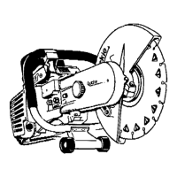
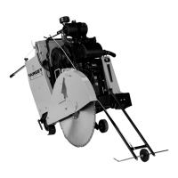
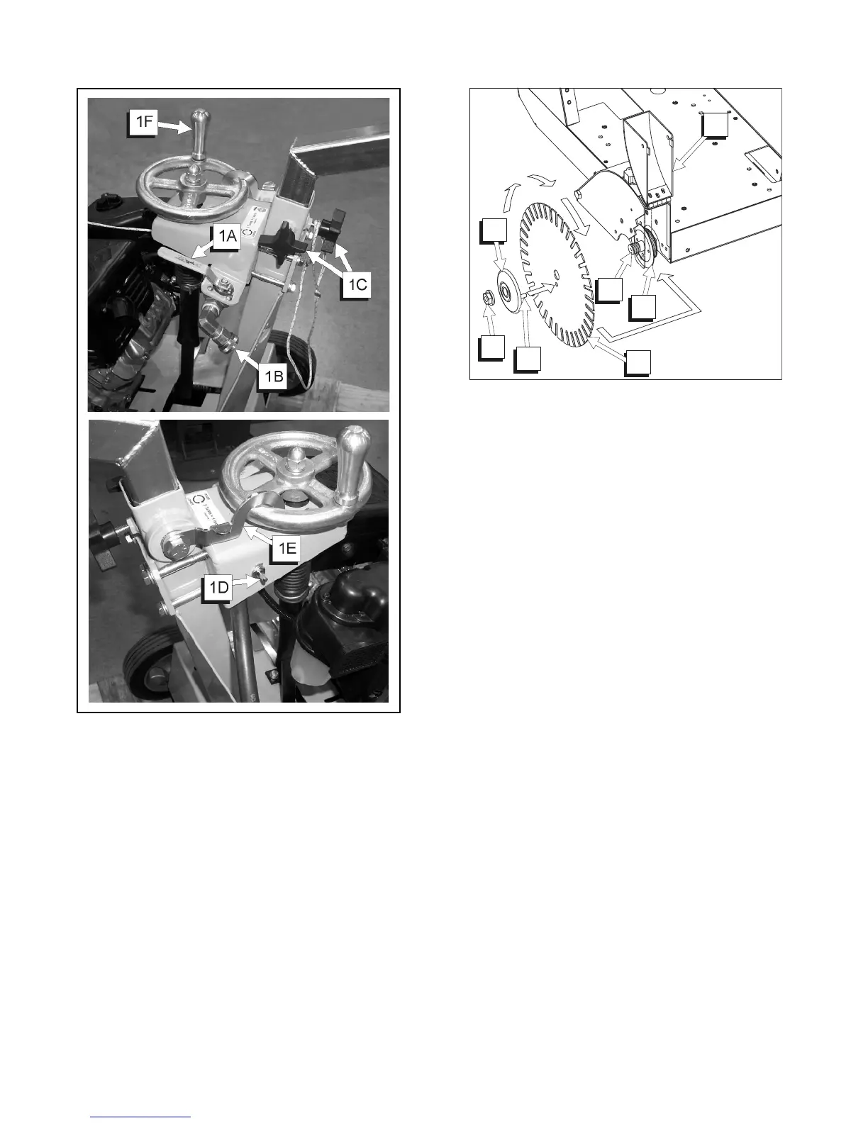
FIGURE 2
2A. BLADE SHAFT NUT: Use to tighten the outer flange
against the diamond blade.
2B. OUTER FLANGE: Use to hold the diamond blade in
position.
2C. NOT USED
2D. LOCKING PIN: Use to prevent the diamond blade
from rotating on the shaft during operation.
2E. DIAMOND BLADE: Use as the cutting tool for
concrete and asphalt surfaces.
2F. INNER FLANGE: Inside support used to hold the dia-
mond blade in position.
2G. NOT USED
2H. BLADE GUARD FRONT: The front section of the
blade guard.
2I. BLADE SHAFT: Supports the blade flanges and blade.
2D
2E
2H
2B
2 I
2F
2A
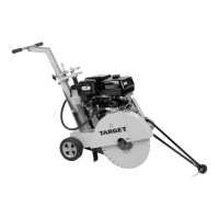
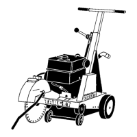
FIGURE 1
1A. WATER VALVE: Use to control the water supply to
the diamond blade.
1B. WATER INLET: Connect water hose at this garden
hose connection.
1C. HANDLE ADJUSTMENT KNOBS: Use to adjust
handle height.
1D. ENGINE STOP SWITCH: Stop Switch: Push down
to stop engine.
1E. DEPTH CONTROL LOCK: Use to lock the position
of the Depth Control Hand Wheel.
1F. DEPTH CONTROL HAND WHEEL: Controls
lowering and raising of the blade into and out of the