2 – Names and Functions of Parts
Rear panel
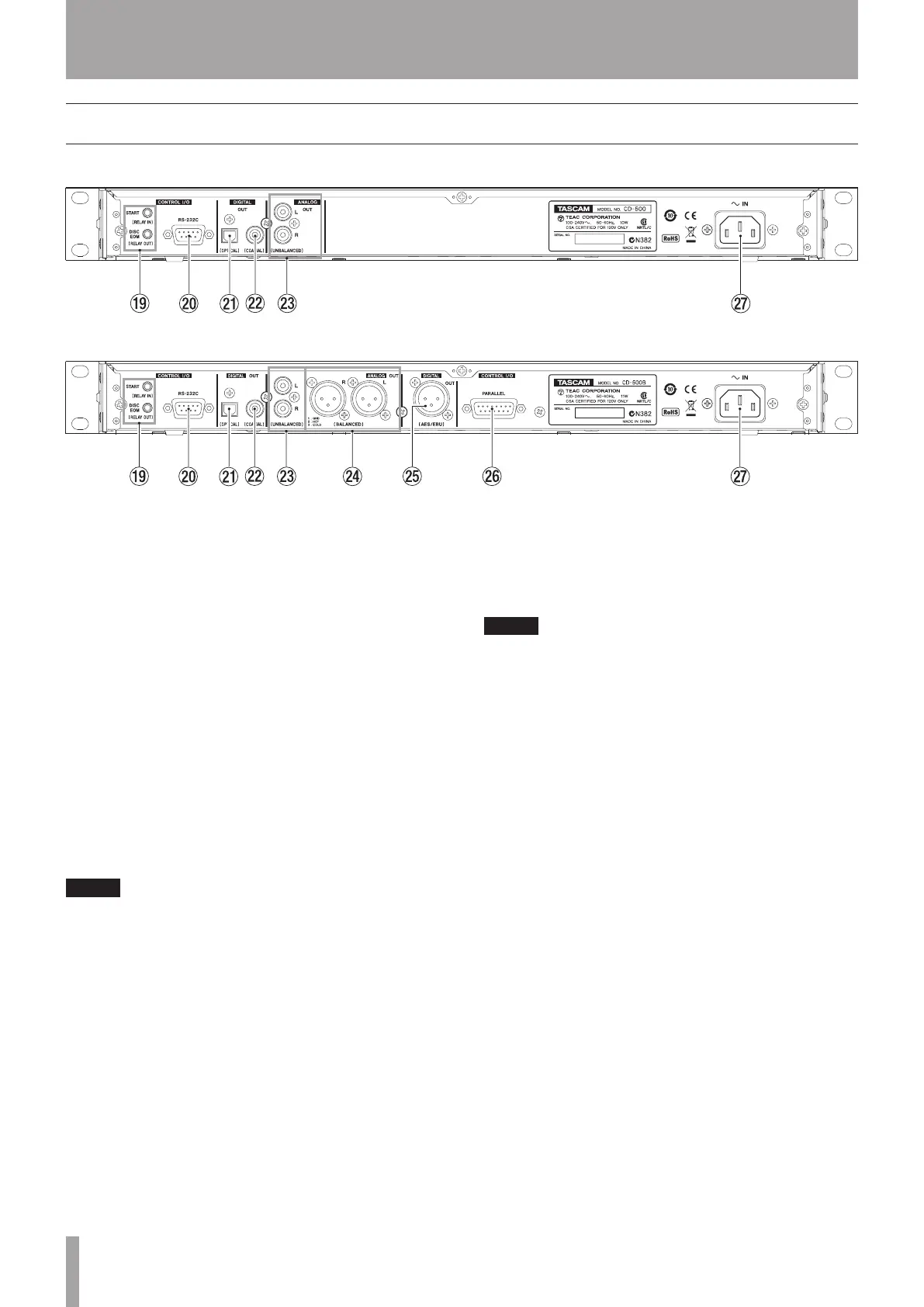
CD-500 rear panel
CD-500B rear panel
o CONTROL I/O START (RELAY IN) and DISC EOM
(RELAY OUT) jacks (3.5-mm mini-jacks)
Use these jacks for fader start and event start, as well
as for relay playback of multiple CD-500 and CD-500B
units. (See “Relay playback” on page 30 and “Fader and
event start” on page 32.)
p CONTROL I/O RS-232C connector
This is a D-sub 9-pin RS-232C serial control connector.
Connect an external controller, for example, here. (See
“Using the RS-232C connector” on page 33.)
a DIGITAL OUT (OPTICAL) connector
The digital CD playback signal is output in S/PDIF
format.
s DIGITAL OUT (COAXIAL) connector
The digital CD playback signal is output in S/PDIF
format.
NOTE
When playing back MP3 or WAV files, the sampling
•
frequency of this unit’s digital outputs is 44.1 kHz.
When using the pitch control function while playing
•
an audio CD or another disc with MP3 or WAV files, the
digital output is at a fixed sampling frequency of 44.1
kHz.
d ANALOG OUT (UNBALANCED) jacks
These are analog outputs for the CD playback signal.
The maximum output level is +6 dBV.
f ANALOG OUT (BALANCED) connectors (CD-500B
only)
These are balanced analog outputs for the CD
playback signal. The maximum output level is +20 dBu.
(1: GND, 2: HOT, 3: COLD)
g DIGITAL OUT (AES/EBU) connector (CD-500B only)
This is a balanced digital audio XLR connector that
outputs AES3-2003/IEC 60958-4 (AES/EBU) format.
NOTE
If the signal is not output from this connector correctly,
confirm that the “22 U-DATA” menu item is set to “OFF”. (See
“User data settings” on page 34.)
h CONTROL I/O PARALLEL connector (CD-500B only)
This is a D-sub 25-pin parallel control connector. Use
this to connect an external controller, for example. (See
“Fader start and stop” on page 32 and “Using parallel
control” on page 34.)
j AC IN connector
Connect the included power cord here.