Do you have a question about the Tascam DA-30 mk II and is the answer not in the manual?
Explanation and remedies for specific error codes displayed by the unit.
Important safety and handling guidelines for the mechanism assembly.
Step-by-step instructions for disassembling the main mechanical block.
Detailed steps for disassembling the base mechanism unit.
Further steps for disassembling the base mechanism unit.
Initial steps for disassembling the cassette holder unit.
Further steps for disassembling the cassette holder unit.
Final steps for disassembling the cassette holder unit.
How to adjust the back tension torque of the tape.
Steps to ensure proper tape path and travel through the mechanism.
Adjusting the data strobe system for proper data timing.
Adjusting and verifying the servo system's performance.
Verifying torque during Fast Forward and Rewind operations.
Steps to ensure proper tape path and travel through the mechanism.
Calibrating the TACH signal for accurate speed monitoring.
Setting the signal level for envelope detection.
Verifying and adjusting the current used for recording.
Verifying and adjusting the record signal level for PCM data.
Verifying playback signal level for ATF data.
Verifying and adjusting the record signal level for ATF data.
Checking and adjusting error rates during recording and playback.
Verifying the output level of the playback signal.
Checking the frequency response characteristics of the playback signal.
Measuring the playback signal's distortion factor.
Measuring the signal-to-noise ratio of the playback signal.
Checking the channel separation of the playback audio.
Setting the minimum input level for the LINE input.
Setting the nominal input and output levels for LINE.
Checking the frequency response of the monitor system.
Verifying the operation of the level meter indicator.
Checking the output level for the headphone jack.
Checking the output level during record/play operations.
Checking the frequency response during record/play.
Measuring the signal-to-noise ratio during recording.
Measuring the dynamic range during record/play.
Checking channel separation during record/play.
Measuring the distortion factor during record/play.
Diagram showing the first part of the exploded assembly.
Detailed list of parts for the fourth exploded view.
Diagram showing the second part of the exploded assembly.
Diagram showing the third part of the exploded assembly.
List of accessories provided with the unit.
Continuation of the fourth exploded view diagram and parts list.
Diagram showing the fourth part of the exploded assembly.
Further continuation of the fourth exploded view parts list.
Component layout and identification for the Audio PCB.
Component layout and identification for the Digital Servo PCB.
Component layout and identification for the Head Phones PCB.
Component layout and identification for the Shuttle PCB.
Component layout and identification for the Front PCB.
Component layout and identification for the Trans PCB.
Component layout and identification for the Reg 1 PCB.
Component layout and identification for the Reg 2 PCB.
Steps for removing the cylinder head assembly from the unit.
Steps for installing the cylinder head assembly, including precautions.
| Type | DAT Recorder |
|---|---|
| Tape Speed | 8.15 mm/s |
| Quantization | 16-bit linear |
| Power Supply | AC 120V, 60Hz |
| Frequency Response | 20Hz - 20kHz ±0.5dB |
| Signal to Noise Ratio | 92 dB |
| Dynamic Range | 92 dB |
| Analog Inputs | RCA, XLR |
| Analog Outputs | RCA, XLR |
| Digital Inputs | Coaxial, Optical |
| Digital Outputs | Coaxial, Optical |
| Sampling Frequency | 32 kHz, 44.1 kHz, 48 kHz |
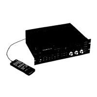
| Remote Control | Wired remote |