EasyManua.ls Logo

Tascam 38 User Manual

Tascam 38
99 pages
To Next Page IconTo Next Page
Page #1 background imageLoading...
Page #1 background image

Table of Contents

Question and Answer IconNeed help?

Do you have a question about the Tascam 38 and is the answer not in the manual?

Tascam 38 Specifications

General IconGeneral
Track Format8-track
EqualizationNAB
Tape Speed15 ips (inches per second)
Reel Size10.5 inch
Frequency Response40 Hz to 22 kHz ±3 dB
HeadsErase, Record, Playback
Track Configuration8-track, half-inch tape
Inputs8 x RCA
Outputs8 x RCA
Wow and Flutter0.06% WRMS

Summary

FEATURES AND CONTROLS

Operational Controls and Indicators

Transport Controls and Indicators

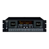
Play, stop, record, pause, and status indicators.

Entering "Record" Mode

Using Output and Function Select Buttons

How to use these buttons to determine record status.

Punch-In Recording Techniques

Methods for making corrections during recording.

Thread Tape and Remote Pedal Operation

Thread the Tape Instructions

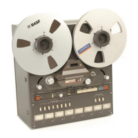
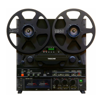
Instructions on how to load tape onto the machine.

Connecting and Operating the DX-4D

DX-4D Hookup Procedure

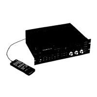
Steps for connecting two DX-4D units for eight channels.

M-30 Recording Mixer Features Overview

M-30 Input Section Capabilities

Describes the various input options and controls.

TASCAM M-30 Technical Specifications

M-30 Input/Output Electrical Specs

Detailed electrical and frequency specifications for inputs/outputs.

TASCAM 38 Mechanical Specifications

Mechanical Specifications Details

Details on tape format, reel size, speeds, and dimensions.

TASCAM 38 Electrical Specifications and Options

Electrical Specifications and Options

Voltage requirements, mounting, and remote control options.

MAINTENANCE Section Overview

THEORY OF OPERATION - Logic and Control IC

Reel Motor Drive Circuit Operation During Playback

Reel Motor Drive Circuit Schematics

Tape Direction Sensing and Counter Clock Generation

FF, REW, and Electrical Brake Operations

Electrical Brake System and FF/REW Control Logic

FF and REW Mode Operation Control Circuits

Counter Zero Return Functionality

Counter Zero Return Control Circuit Diagram

Punch In/Out Control Circuit Operation

Amplifier Circuit Description Overview

Amplifier Circuit Details - Bias and Record Control

Reproduce Amplifier Circuit Operation

Reproduce Amplifier Modes Explained

2. CHECKS AND ADJUSTMENTS Section

Essential Test Equipment Required List

Lists necessary test equipment for calibration.

Removing the Panels of the Deck

Capstan and Brake Adjustments Procedures

Reel Motor Torque Measurement and Adjustment

Reel Motor Torque Measurement Steps

Details on measuring take-up torque and back tension.

Back Tension and Pinch Roller Pressure Adjustments

Back Tension Adjustment Method

How to adjust back tension using a spring scale.

Pinch Roller Pressure Measurement

How to measure and set pinch roller pressure.

Reel Table, Tape Speed, and Wow/Flutter Checks

Record/Reproduce Amplifier Checks and Alignment

Tape Path and Head Contact Alignment

Procedures for aligning tape path and ensuring head contact.

Head Azimuth Adjustment Guide

How to adjust head azimuth for optimal playback.

Head Alignment and Input Level Calibration

Head Alignment Procedures Using Oscilloscope

Techniques for aligning heads using an oscilloscope.

Meter Calibration and Reproduce Level Settings

Meter Calibration Procedure

How to calibrate the VU meters.

Reproduce Level Calibration Steps

How to calibrate the reproduce signal levels.

Reproduce Frequency Response Adjustment

How to check and adjust frequency response.

Frequency Response and Bias Adjustments

Reproduce Frequency Response Check

How to measure frequency response in REPRO and SYNC modes.

Bias Tuning and Trap Adjustments

Procedures for bias tuning and trap adjustments.

Recording Bias Adjustment Method

How to adjust recording bias.

Recording Level and Overall Frequency Response

Recording Level Adjustment Steps

How to adjust recording signal levels.

Overall Frequency Response Check

How to check overall frequency response.

Signal-to-Noise Ratio Measurement

How to measure signal-to-noise ratio.

Erase Ratio, Crosstalk, and Distortion Checks

Erase Ratio Measurement Procedure

How to measure the erase ratio.

Adjacent Channel Crosstalk Measurement

How to measure crosstalk between adjacent channels.

Distortion Measurement Procedure

How to measure audio distortion.

3. EXPLODED VIEWS AND PARTS LISTS

Exploded Views and Parts Lists of 38

Visual breakdown of the unit with corresponding part numbers.

4. PC BOARDS AND PARTS LISTS

5. SCHEMATICS Section

Wiring Circuit Diagram

Overall wiring diagram showing PCB interconnections.

Head Assembly Circuit Diagram

Head PCB to Mother PCB Connections

Diagram detailing head connections to the main PCB.

Related product manuals