EasyManua.ls Logo

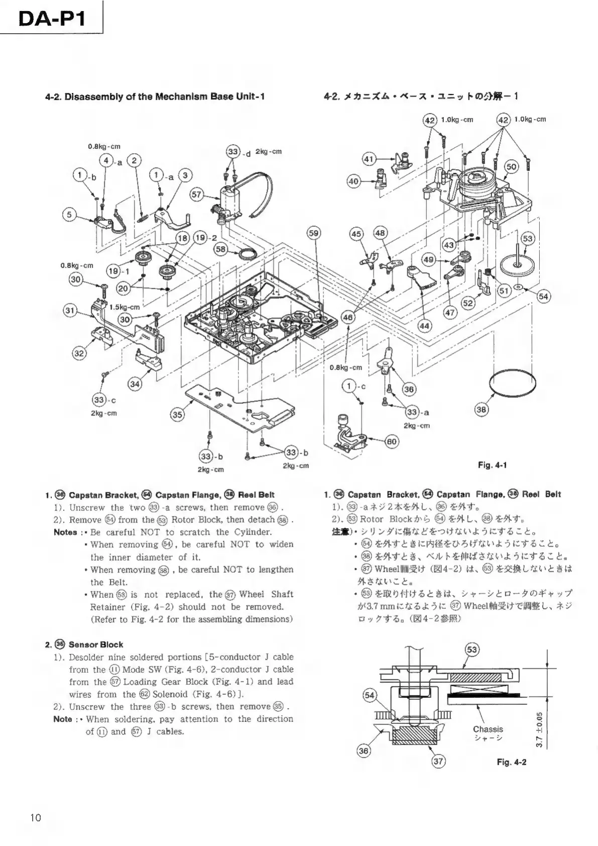
Tascam DA-P1 - Mechanism Disassembly - Part 1; Capstan Bracket, Flange, and Belt Removal; Sensor Block Removal

Tascam DA-P1
59 pages
Print Icon
To Next Page IconTo Next Page
To Previous Page IconTo Previous Page
Loading...
DA-P1
4-2.
Disassembly
of
the
Mechanism
Base
Unit-1
42.
メ
カニ ズム
・
ベ
ー
ス
・
ユ
ニッ
ト
の
分
解
1
Fig.
4-1
1.
@
Capstan
Bracket,
@
Capstan
Flange,
@
Reel
Belt
1.
69
Capstan
Bracket,
©
Capstan
Flange,
@®
Reel
Belt
1).
Unscrew
the
two
@)-a
screws,
then
remove
(9)
.
D.
G9-a
X
Z
24
AU,
G9
Es
2).
Remove
69
from
the
(3)
Rotor
Block,
then
detach
(3)
.
2).
@
Rotor
Block
か
ら
⑥)
を
外し
、
)
を
外す
。
Notes
:+
Be
careful
NOT
to
scratch
the
Cylinder.
注意
)・
シ
リン
ダ
に
傷
な
ど
を
つけ
な
いよ
うに
する
こと
。
+
When
removing
@,
be
careful
NOT
to
widen
・⑥》
を
外す
と
き
に
内
径 を
ひろ
げ な
いよ
うに
する
こと
。
the
inner
diameter
of
it.
・@9
を
外す
と
き
、
ベ
ルト
を
伸ばさ
な
いよ
うに
する
こと
。
+
When
removing
@)
,
be
careful
NOT
to
lengthen
・⑥)
Wheel
四
受け
(
図
4-2)
は
、
⑥
を
交換
し
な
いと
き
は
外さ
な
いこ
と
。
is
not
replaced,
the
@)
Wheel
Shaft
・@)
を
取り
付け
る
と
き
は
、
シ
ャ
ー
シ
と
ロー
タ
の
ギャ
ッ
プ
Retainer
(Fig.
4-2)
should
not
be
removed.
が
3.7
mm
に な
る
よう
に
Wheel
軸受
け で
調整
し
、
ネジ
(Refer
to
Fig.
4-2
for the
assembling
dimensions)
ロッ
ク
す
る
。(
図
4-2
参照)
2.@
Sensor
Block
к
1).
Desolder
nine
soldered
portions
[5-conductor
J
cable
p
from
the
(D
Mode
SW
(Fig.
4-6),
2-conductor
J
cable
="
—
3
from
the
67
Loading
Gear
Block
(Fig.
4-1)
and
lead
Y {
wires
from
the
@
Solenoid
(Fig.
4-6)].
55)
—
2).
Unscrew
the
three
@3)-b
screws,
then
remove
@)
.
Note
:+
When
soldering,
pay
attention
to
the
direction
III]
ОШ
of
@)
and
€)
J
cables.
ER
Chassis
シャ
ー
シ
©
D
Fig.
4-2
|
3.7
+0.05