EasyManua.ls Logo

Tascam DA-P1 - Mechanism Disassembly - Part 1; Sensor Block, Spacer Removal; TU Assembly Removal; BT Arm Assembly Disassembly

Tascam DA-P1
59 pages
Print Icon
To Next Page IconTo Next Page
To Previous Page IconTo Previous Page
Loading...
з.
@
Sensor
Block,
@
ID
Spacer
(L),
@
ID
Spacer
(R)
1).
Unscrew
the
@3)-c
screw.
2).
Unscrew
the
two
&)
screws,
then
remove
6D,
&2,
апа
69.
Note
:+
When
reinstalling,
be
careful
NOT
to
tighten
the
@
screw
slantwise
(because
the
switch
is
mounted
obliquely).
4.
(9
-1
TU
Ass
y,
())
-2
TU
Ass'y
1).
Remove
the
two
(8)
washers,
detach
@-1
and
(9-2.
Note
:+
When
reinstalling
(9)-1
and
(9-2,
apply
Molicoat
to
the
shaft.
5.
(3)
BT
Arm,
(2)
BT
Spring,
()
BT
Band
Ass'y
1).
Remove
the
Ф-а
washer,
then
disengage
O.
2).
Remove
the
hook
of
Кол
@,
then
detach
@.
3).
Remove
the
@-b
washer
and
the
@-a
screw,
then
detach
©.
Notes
:-
Pay
attention
NOT
to
deform
the
band
of
©.
+
Refer
to
item
5-1
for
the
Back
Tension
Torque
adjustment.
6.
@
Loading
Lever
Block
1).
Remove
the
@-c
washer,
then
remove
60)
.
7.
@
Cylinder
Ass'y,@TG-R
Spring,
@
TG-R,
@
Gear
Arm,
@
L1
(IN)
Arm,
@9
L1
(OUT)
Arm,
@
Rotor
Block,
@
Loading
Link
Block,
@
INC
Base
(IN),
@
Loading
Link
Block,
@
INC
Base
(OUT)
1).
Unscrew
the
six
@
screws,
turn
the
Mechanism
Base
Unit
upside
down,
then
remove
60)
with
3)
pushed
downward.
Remove
@, @,
@,
©),
and
@
from
&),
in
this
order.
3).
Pull
out
63)
from
4).
Unscrew
the
two
@)
screw,
then
remove
@,@,@,
@
from
.
Notes
:-
Be
careful
NOT
to
scratch
the
Cylinder.
+See
that
the
phases
of
@,@),and
@
are
matched
with
each
other,
as
shown
in
Fig.
4-3.
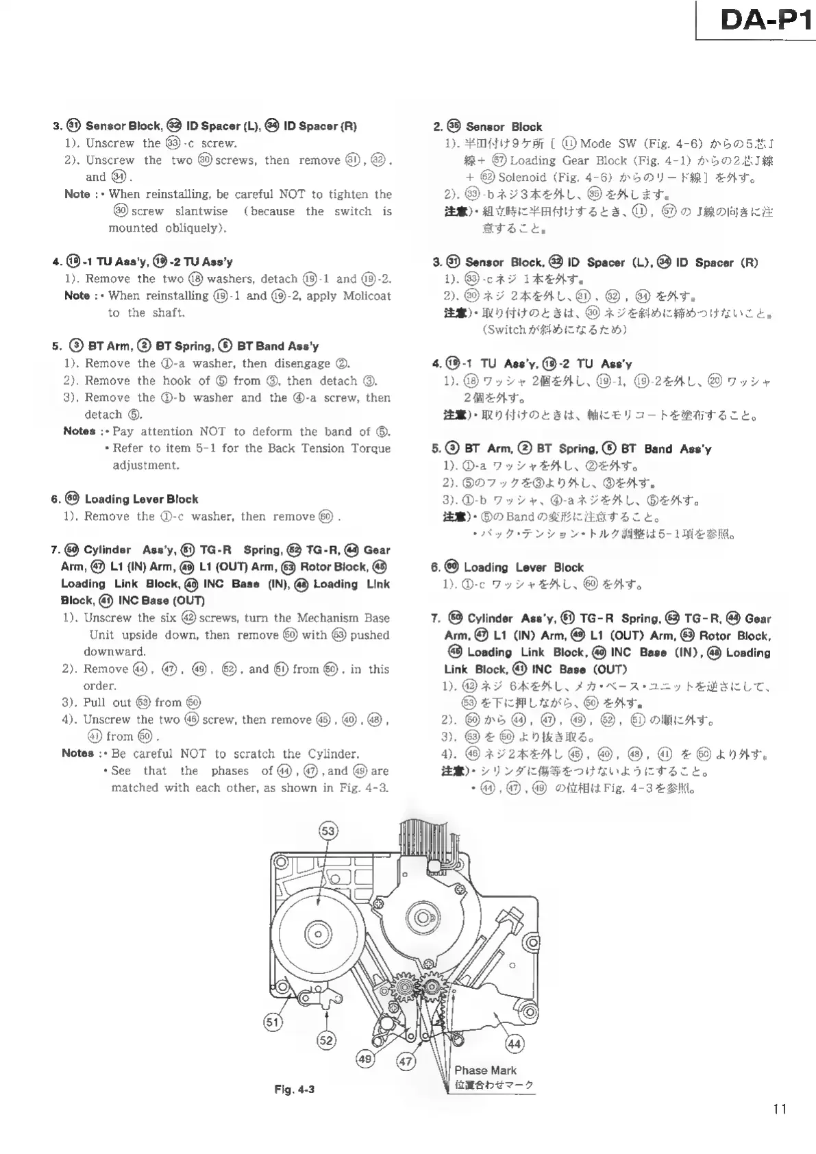
2).
Fig.
4-3
DA-P1
2.
6)
Sensor
Block
1).
半田
付け
9
ケ所
[
@
Mode
SW
(Fig.
4-6)
/^50545J
#1
+
©)
Loading
Gear
Block
(Fig.
4-1)
/^
500215148
+
@
Solenoid
(Fig.
4-6)
250)
—
KR]
EAT.
2).
⑲⑬
-b
ネ
ジ
3
本
を
外し
、
Ө
を
外し
ます
。
注意
)・
組
立
時
に
半田
付け
する
と
き
、⑬
,
@
о
線
の
向き
に
注
意
する
こと
。
3.
@
Sensor
Block,
(2
ID
Spacer
(L),
@
ID
Spacer
(R)
1).
⑬
-c
ネジ
1
本
を
外す
。
2).
@
ネジ
2
本
を
外し
、⑥D
,
)
,
⑥
を
外す
。
注意
)・
取
り
付け
の
と
き
は
、@)
ネジ
を
斜め
に
締め
つけ
な
いこ
と
。
(Switch
が
斜め
に な る た
め )
4.(9-1
TU
Ass'y,
(3-2
TU
Ass'y
1).
⑲
ワッ シャ
2
個
を
外し
、
⑲-1,
(9-22AU.
QU
o
ze
2
個
を
外す
。
注意
)・
取 り
付け
の
と
き
は
、
軸
に
モリ
コー
ト
を
塗布
する
こと
。
5.③
BT
Arm,
(2
BT
Spring,
(5)
BT
Band
Ass'y
1.①-a
ワッ
シャ
を
外し
、②
を
外す
。
2).
⑤
の
フッ
ク
を
③
よ
り
外
し
、③
を
外す
。
3).①-b
ワッ
シャ
、④-a
ネジ
を
外し
、⑤
を
外す
。
ER):
OO
Band
O
i
・
バ
ッ
ク
・
テ
ンション
・
ト
ルク
調整
は
5-
1
項 を
る
6.@
Loading
Lever
Block
1).
①-c
ワッ
シャ
を
外し
、⑥9)
を
外す
。
7.
(9)
Cylinder
Ass'y,
€)
TG-R
Spring,
É)
TG-R,
(Y)
Gear
Arm,
(8)
L1
(IN)
Arm,
&9
L1
(OUT)
Arm,
®
Rotor
Block,
@
Loading
Link
Block,
@
INC
Base
(ІМ).
(9)
Loading
Link
Block,
@
INC
Base
(OUT)
1).
⑱⑲
ネジ
6
本
を
外し
、
メ
カ
・
ベ
ー
ス
・
ユ
ニッ
ト
を
逆さ
に
し
て
、
3
を
下
に
押し
な
が ら
、
⑥⑯)
を
外す
。
69
и
6),
®,
49,
69,
бі)
Ос
2%
を
⑯)
より
抜き
取る
。
ジ
2
本
を
外し
@, @,
⑯
を
より
外す
。
注意
)・
シ
リン
ダ
に
傷
等 を
つけ
な
いよ
うに
する
こと
。
-
9,
⑰
,
⑲
の
位相
は
Fig.
4-3
を
参照
。
Phase
Mark
位置
合わ
せ
マ
ー
ク