EasyManua.ls Logo

Tascam DA-P1 - Mechanism Disassembly - Part 2; Sensor Block Removal (2); Sensor Block and Spacer Removal (2); TU Assembly Removal (2)

Tascam DA-P1
59 pages
Print Icon
To Next Page IconTo Next Page
To Previous Page IconTo Previous Page
Loading...
DA-P1
2.@Brake
Spring,
@
Loading
Lever
Block,
(SU
Brake
Arm
1).
Disengage
(5).
2).
Remove
the
two
@-d
washers,
then
detach
(Wand
(23.
3.
@
Reel
Ass’y(SU),
@
Ree!
Ass’y(TU),
@
SU
Reel
Spring
1).
Take
off
the
two
(D-e
washers,
then
remove
@
,
(3)
,
two
(2)
,
and
two
(6)
washers.
Notes
:*
Apply
Molicoat
to
the
spindle
when
reinstalling
(3
and
(9
.
*
See
that
no
Molicoat
is
applied
to
the
reflector
plate
of
Wand.
+See
that
the
serrated
portion
of
апа
(3)
із
free
from
Molicoat
coating,
scratches
and
indentation.
4.@ldle
Spring,
@ldle
Gear,
@Center
Pulley,
@)
Cam
Plate,
@Idle
Cam,@Cam
Plate
Spring,
(BT
Lever
Spring,
(7)
BT
Lever,
(3)
BT
Cam
Lever
1).
Take
off
the
@-f
washer,
then
remove
@i)
and
@)
.
2).
Remove
the
@-g
washer,
then
detach
69
апа
69
washer.
3).
Disengage
@)
from
the
hook,
remove
(28)
and
€?)
,
then
take
off
@).
4).
Disengage
©.
5).
Remove
the
®-h
washer,
then
detach
@
and
©.
Notes
:-
Apply
Molicoat
to
the
spinde
when
incorporating
@3)
.
+
When
reinstalling
@6),
apply
Molicoat
to
two
oblong
holes
and
the
spring
hook.
5.
(8)
Worm
Wheel,
(8)
Center
Gear,
(1)
Mode
Gear,
(9)
Mode
Cam,
@
Mode
Switch
1).
Remove
the
three
@-i
washers,
then
detach
69)
,
66)
,
®, ®,
and
®,
in
this
order.
Notes
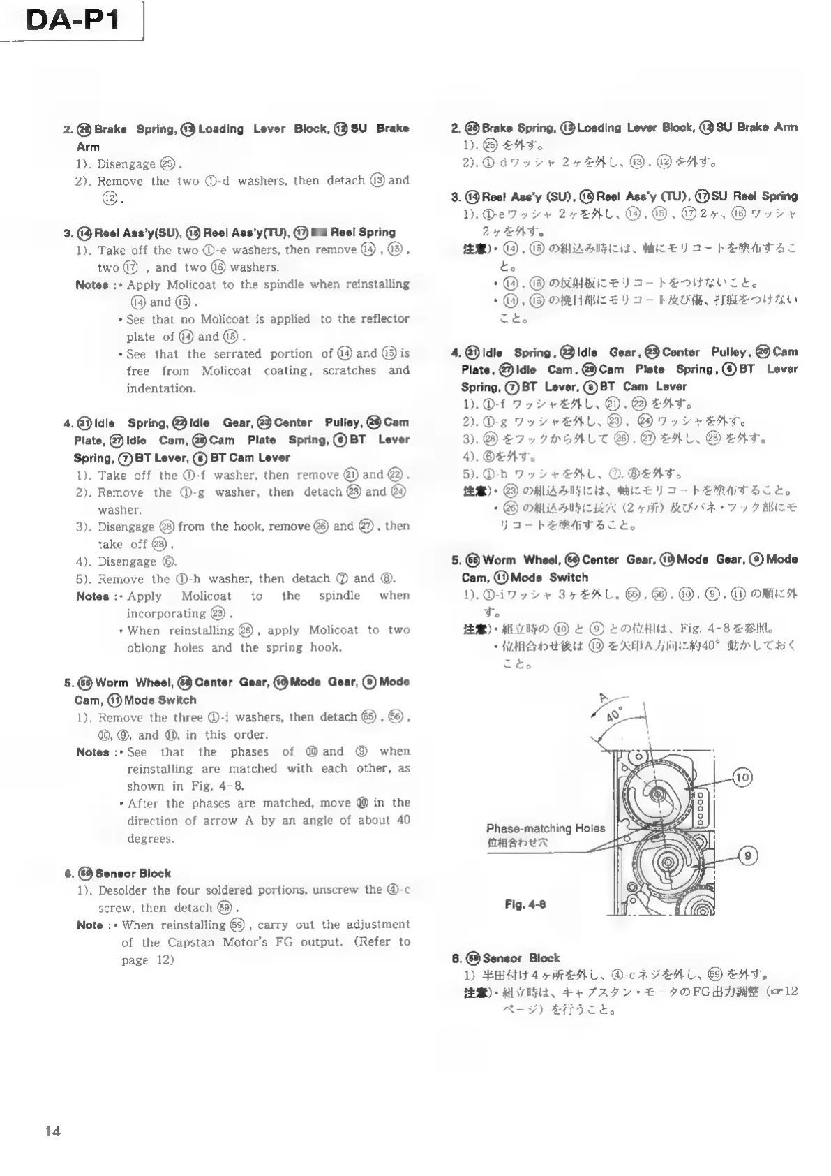
:+See
that
the
phases
of
@and
(9
when
reinstalling
are
matched
with
each
other,
as
shown
in
Fig.
4-8,
*
After
the
phases
are
matched,
move
db
in
the
direction
of
arrow
A
by
an
angle
of
about
40
degrees.
6.
6%
Sensor
Block
1).
Desolder
the
four
soldered
portions,
unscrew
the
@-c
screw,
then
detach
69.
Note
:+
When
reinstalling
69)
,
carry
out
the
adjustment
of
the
Capstan
Motor's
FG
output.
(Refer
to
page
12)
2.
@
Brake
Spring,
@
Loading
Lever
Block,
(3
SU
Brake
Arm
1).
⑯
を
外す
。
2).①-d
ワッシャ
2
ヶ
を
外し
、⑬,
⑬
を
外す
。
3.
@Reel
Ass’y
(SU),
(i
Reel
Ass’y
(TU),
@SU
Reel
Spring
1).①-e
ワ
ッ
シ
ャ
2
ヶ
を
外し
、⑬,
⑮
、⑰
2
ヶ
、⑯
ワッ
シャ
2
ヶ
を
外す
。
28):
O,
⑬
の
組込み
時 に は 、
軸
に
モリ
コー
ト
を
深
布
する
こ
to
・(⑩⑭
,
⑯⑬
の
反射
板
に
モリ
コー
ト
を
つけ
な
いこ
と
。
*
@
,
⑯
の
挽
目
部
に
モリ
コー
ト
及
び
傷
、
打
痕
を
つけ
な い
са.
4.@ldle
Spring,
ldlo
Gear,
(E)
Center
Pulley,
E)
Cam
Plate,
@ldie
Cam,
@)Cam
Plate
Spring,
(BT
Lever
Spring,
(2)
BT
Lever,
(S)BT
Cam
Lever
1).
O-f
D7
7+
EAL,
@,
⑬
を
外す
。
2).①-g
ワッ
シャ
を
外し
、@)
,
@
ワッ
シャ
を
外す
。
3).
を
フッ
ク
か
ら
с
@,@
を
外し
、
@)
を
外す
。
4.⑥
を
外す
。
5).①-h
ワッ
シャ
を
外し
、⑦,
を
外す
。
注意
)・@⑬)
の
組込み
時
に
は
、
軸
に
モリ
コー
ト
を
次
布
す
る
こと
。
*
@
の
組込み
時
に
長
穴
(2
ヶ所
)
及び
パネ
・
フ
ッ
ク
部
に
モ
リコ
ー
ト
を
塗布
する こと
。
5.
@
Worm
Wheel,
@
Center
беаг,
(9
Мофе
Сеаг,
($)
Моде
Сат,
@
Моде
Switch
1).①-1
ワ
ッ
シ
ャ
3
ヶ
を
外し
、
,
⑥⑯
.
⑩
.
⑨,
⑩
の
順に
外
す
。
注意
)・
組
立
時
の
@@
と
O)
と
の
位相
は
、Fig.
4-8
を
参照
。
\
相
合わ
せ 後
は
⑩
を
矢印
方
向
に
約
40*
動か
し て お く
こと
。
Phase-matching
Holes
MER
A
Fig.
4-8
6.
@Sensor
Block
1)
半田
付け
4
ヶ所
を
外し
、④-c
ネ
ジ
を
外し
、@9)
を
外す
。
注意
)・
組
立
時
は
、
キ
ャ
プス
タン
・
モ
ー
タ
の
FG
出
力
調整
(12
ペー
ジ
)
を
行う
こと
。