EasyManua.ls Logo

Tascam DA-P1 - Electrical Adjustments; TACH Adjustment; Envelope Detection Level Adjustment; ATF Gain Adjustment

Tascam DA-P1
59 pages
Print Icon
To Next Page IconTo Next Page
To Previous Page IconTo Previous Page
Loading...
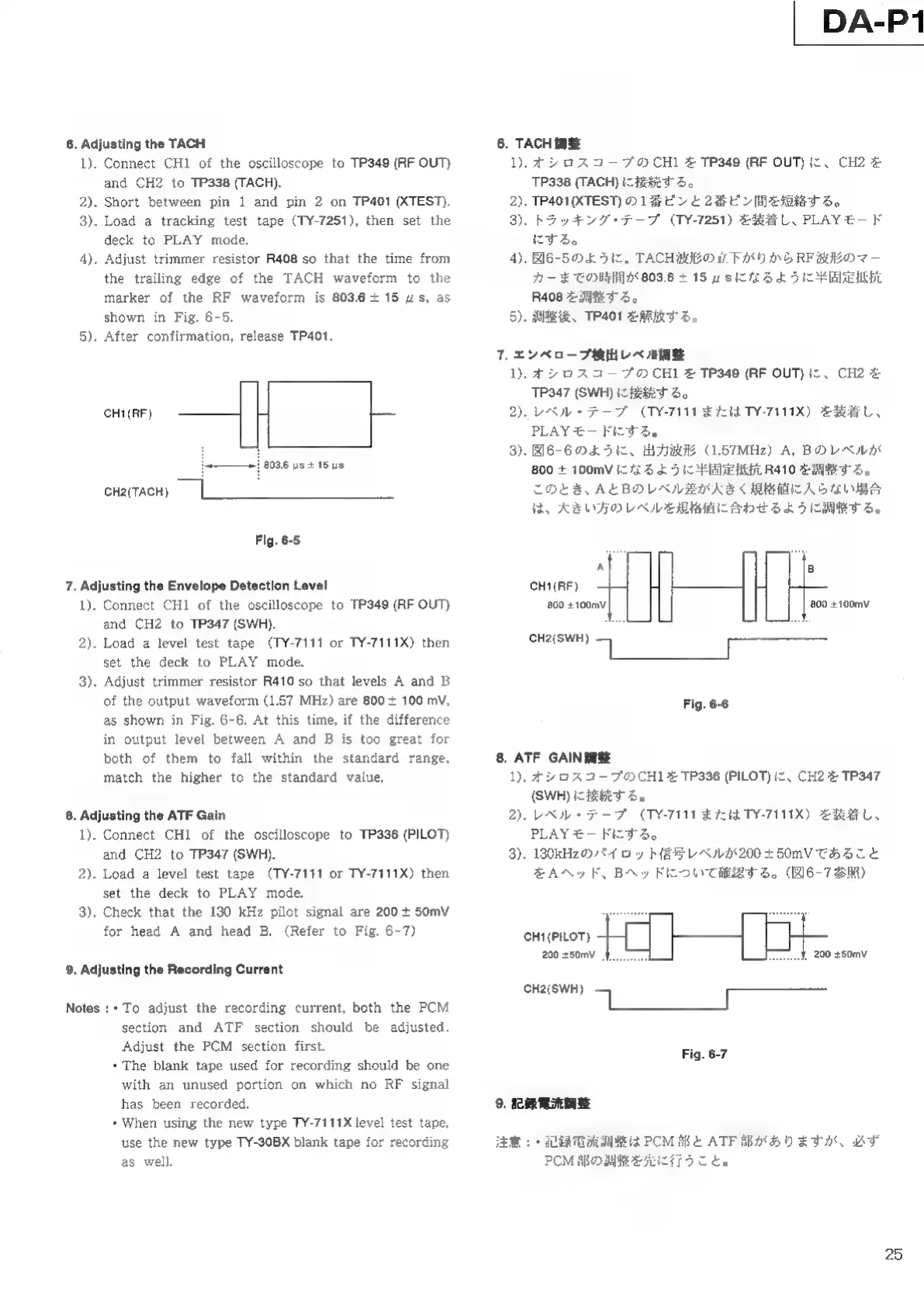
6.
Adjusting
the
TACH
1).
Connect
CH1
of
the
oscilloscope
to
TP349
(RF
OUT)
and
CH2
to
TP338
(TACH).
2).
Short
between
pin
1
and
pin
2
on
TP401
(XTEST).
3).
Load
a
tracking
test
tape
(TY-7251),
then
set
the
deck
to
PLAY
mode.
Adjust
trimmer
resistor
R408
so
that
the
time
from
the
trailing
edge
of
the
TACH
waveform
to
the
marker
of
the
RF
waveform
15
803.6
+
15
из,
а5
shown
in
Fig.
6-5.
After
confirmation,
release
TP401.
4).
5).
cHt(RF)
——
H
I
++!
803.6
us
+15
us
CH2(TACH)
Fig.
6-5
7.
Adjusting
the
Envelope
Detection
Level
1).
Connect
CHI
of
the
oscilloscope
to
TP349
(RF
OUT)
and
CH2
to
TP347
(SWH).
2).
Load
a
level
test
tape
(TY-7111
or
TY-7111X)
then
set
the
deck
to
PLAY
mode.
3).
Adjust
trimmer
resistor
R410
so
that
levels
A
and
B
of
the
output
waveform
(1.57
MHz)
аге
800
+
100
mV,
as
shown
in
Fig.
6-6.
At
this
time,
if
the
difference
in
output
level
between
A
and
B
is
too
great
for
both
of
them
to
fall
within
the
standard
range,
match
the
higher
to
the
standard
value.
8.
Adjusting
the
ATF
Gain
1).
Connect
СНІ
ої
(пе
oscilloscope
to
TP336
(PILOT)
and
CH2
to
TP347
(SWH).
2).
Load
a
level
test
tape
(TY-7111
or
TY-7111X)
then
set
the
deck
to
PLAY
mode.
3).
Check
that
the
130
kHz
pilot
signal
are
200
+
50mV
for
head
A
and
head
B.
(Refer
to
Fig.
6-7)
9.
Adjusting
the
Recording
Current
Notes
:*
To
adjust
the
recording
current,
both
the
PCM
section
and
ATF
section
should
be
adjusted.
Adjust
the
PCM
section
first.
+
The
blank
tape
used
for
recording
should
be
one
with
an
unused
portion
on
which
no
RF
signal
has
been
recorded.
*
When
using
the
new
type
TY-7111X
level
test
tape,
use
the
new
type
TY-30BX
blank
tape
for
recording
as
well.
DA-P1
6.
ТАСН
1).
オ
シロ
スコ
ー
プ
の
CH1
を
TP349
(RF
OUT)
iz,
CH2
€
TP338
(TACH)
に
接続
する
。
2).
TP401(XTEST)
の
1
番
ピ
ン
と
2
番
ピ
ン
間
を
短絡
する
。
3).
トラ
ッ
キ
ング
・ テ ー
プ
(TY-7251)
を
装着
し
、
PLAY
モ
ー
ド
に
する
。
4).
図
6B-5
の
よう
に
、
TACH
波
形
の
立
下
が
りか
ら
RE
波
形
の
マー
カー
まで
の
時
間
が
803.6
よ
15
ys
に
な
る
よう
に
半
固定
抵抗
R408
を
調整
する
。
5).
調整
後
、TP401
を
解放
する
。
7.
エン
ベロ
ー
プ
検出
レベ
ル
調
整
1).
オ
シロ
スコ
ー
プ
の
CH1
を
TP349
(RF
OUT)
に
、CH2
を
TP347
(SWH)
に
接続
する
。
2).
レベ
ル
・
テ
ー
プ
(TY-7111
また
は
TY-7111X)
を
装着
し
、
PLAY
モ
ー
ド
に
する
。
3).
図
6-6
の
よう
に
、
出
力
波形
(1.57MHz)
A,
B
の
レベ
ル
が
800
100mV
に
な
る
よう
に
半
固
定
抵抗
R410
を
調整
する
。
この
と
き
、A
と
B
の
レベ
ル
差
が 大
きく
規格
値 に
入ら
な
い
場
合
は
、
大
きい
方
の
レベ
ル
を
規格
値
に
合わ
せる
よう
に
調整
する
。
|
Ë
CHI(RF)
СЕ
ШЫ
CH2(SWH)
q
AA
Fig.
6-6
8.
ATF
GAIN
調
整
1).
オシ
ロス
コー
プ
の
CH1
を
TP336
(PILOT)
に
、
CH2
を
TP347
(SWH)
に
接続
する
。
2).
レベ
ル
・
テ
ー
プ
(TY-7111
また
は
TY-7111X)
を
装着
し
、
PLAY
モ
ー
ド
に
する
。
3).
130kHz
の
パイ
ロッ
ト
信
号
レ
ベル
が
200
エ
50mV
で
ある
こと
を
4
ヘッ
ド
、B
ヘ
ッ
ド
に
つい
て
確認
する
。(
図
6-7
参照
)
|
200
«боту
CH2(SWH)
р
чан
CH1(PILOT)
200
+50mV
|
Fig.
6-7
9.
記録
電流
調整
:・
記
録
電流
調整
は
PCM
部
と
ATF
部
が
あり
ます
が
、
必
ず
PCM
部
の
調整
を
先
に
行う
こと
。
25