EasyManua.ls Logo

Tascam DA-P1 - Monitor System Measurements; LINE Input;Output Level; Monitor Frequency Response; Headphone Output Level

Tascam DA-P1
59 pages
Print Icon
To Next Page IconTo Next Page
To Previous Page IconTo Previous Page
Loading...
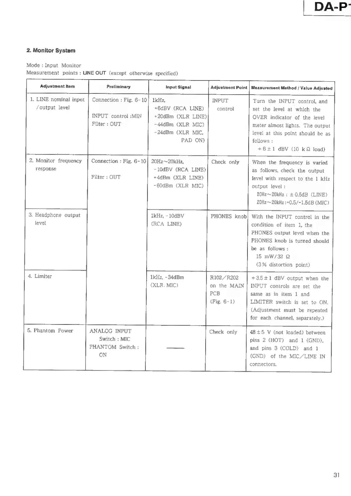
2.
Monitor
System
Mode
:
Input
Monitor
Measurement
points
:
LINE
OUT
(except
otherwise
specified)
DA-P
Adjustment
Item
Preliminary
Input
Signal
Adjustment
Point
Measurement
Method
/
Value
Adjusted
Turn
the
INPUT
control,
and
|
response
3.
Headphone
output
level
4,
Limiter
Filter
:
OUT
~10dBV
(RCA
LINE)
+4dBm
(XLR
LINE)
-60dBm
(XLR
MIC)
1.
LINE
nominal
input
|
Connection
:
Fig.
6-10|
1kHz,
INPUT
/output
level
+6dBV
(RCA
LINE)
control
set
the
level
at
which
the
INPUT
control
:MIN
+20dBm
(XLR
LINE)
OVER
indicator
of
the
level
Filter
:
OUT
-44dBm
(XLR
MIC)
meter
almost
lights.
The
output
-24dBm
(XLR
MIC,
level
at
this
point
should
be
as
PAD
ON)
follows
:
+6+1
dBV
(10
kQ
load)
2.
Monitor
frequency
|
Connection
:
Fig.
6-10]
20Hz~20kHz,
Check
only
When
the
frequency
is
varied
as
follows,
check
the
output
level
with
respect
to
the
1
kHz
output
level
:
20H2~20kHz
:
+
0.5dB
(LINE)
20Hz—
20kliz
:«0.5/-1.5dB
(MIC)
1kHz,
-
10dBV
(RCA
LINE)
PHONES
knob
With
the
INPUT
control
in
the
condition
of
item
1,
the
PHONES
output
level
when
the
PHONES
knob
is
turned should
be
as
follows
:
15
mW/32
Q
(3%
distortion
point)
1kHz,
-
34dBm
(XLR.
MIC)
R102/R202
on
the
MAIN
PCB
(Fig.
6-1)
+3.5
+1
dBV
output
when
the
INPUT
controls
are
set
the
same
as
in
item
1
and
LIMITER
switch
is
set
to
ON.
(Adjustment
must
be
repeated
for
each
channel,
separately.)
5.
Phantom
Power
ANALOG
INPUT
Switch
:
MIC
PHANTOM
Switch
:
ON
Check
only
48
+5
У
(not
loaded)
between
pins
2
(HOT)
and
1
(GND),
and
pins
3
(COLD)
and
1
(GND)
of
the
MIC/LINE
IN
connectors.
31