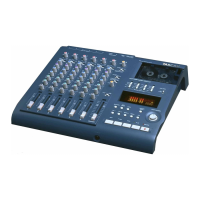
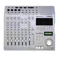
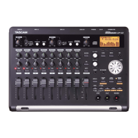
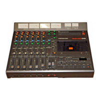
Do you have a question about the Tascam Portastudio 246 and is the answer not in the manual?
Details physical specifications like track format, heads, motors, dimensions, and weight.
Lists mixer and recorder input/output levels, impedance, and headphone specs.
Important notes on dB reference, voltmeter impedance, units, and safety-critical components.
Overview of the amplifier, control, driver, and power supply circuits.
Explains the microcomputer, input/output extension ICs, and switch scanning logic.
Details the record/playback amplifier, dbx encoder/decoder, and bias generator circuits.
Diagrams showing the physical placement of major components within the unit.
Lists specialized tools and test tapes required for calibration and adjustment procedures.
Defines standard voltage, output load, and conditions for performance checks.
Provides instructions on how to disassemble key components like trim covers, mechanism, and heads.
Covers adjustments for capstan thrust, microswitch clearance, and head base position.
Details setting controls and checking signal paths and frequency response in the mixer.
Instructions for adjusting playback level, frequency response, bias, and record level.
Detailed diagrams illustrating the physical arrangement of parts for disassembly and identification.
Lists accessories like owner's manuals supplied with the product.
Detailed list of components for the Record/Playback PCB Assembly.
Detailed list of components for the Input Amplifier PCB Assembly.
Detailed list of components for the Control PCB Assembly (Part A).
Detailed list of components for the Drive PCB Assembly.
Detailed list of components for the Power Supply PCB Assembly.
Visual representation of signal flow and component interconnections across the entire system.
Charts illustrating signal levels and gain stages in various sections of the unit.
Pinouts and logic diagrams for integrated circuits used in the device.
| Brand | Tascam |
|---|---|
| Model | Portastudio 246 |
| Category | Recording Equipment |
| Language | English |