29
I25 I24 I23 I22 I21 I20 I19 I18 I17 I16 tr sv sl pt pl no nl it fr fi es en de da cz
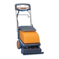
Overview
1 Handle
2 Water pump switch (illuminated)
3 Suction motor switch (non-illuminated)
4 Main switch
5 Transport handle, front
6 Tank unlocking device
7 Filter housing
8 Dosing lid
9 Solution tank
10 Recovery tank
11 Brush pressure regulation
12 Unlocking device for brush holder cover
13 Side bumper
14 Squeegee
15 Front bumper
16 Nozzle body
17 Wheels
18 Foot pedal
19 Suction hose
20 Transport handle, rear
21 Hose connection
22 Power supply cord
23 Cable hook
24 Upper cable-winding hook
25 Protective filter fpr pump
26 Suction chasnnel maintenance cover
27 Sponge filter
Preparation for operation/Operation
Electrical circuit diagram
2
5
6
8
11
24
23
21
20
19
7
10
3
4
9
12
13 14 15 16 17 18
22
2
1
Before the machine can be put into operation, the two parts of the
machine must be connected electrically and the handle must be
screwed onto the body of the machine.
To do this, follow the assembly instruction on Page 2 of these
instructions for operation.
11
10
12
14
13
15
8
6
1
2
5
3
4
9
7
Y/G
WHITE
BLACKBLACK
BROWN
GREEN
WHITE
WHITE
WHITE
BLACK
BLACK
RED
BLUE
GREEN
RED
WHITE
BLACK
GREEN
RED
WHITE
Y/G
BLACK
BROWN
RED
11
10
12
16
16
14
13
15
8
6
1
2
5
3
4
9
7
BLACK
BROWN
Y/G
WHITE
WHITE
Y/G
Y/G
WHITE
BLACK
BLACK
RED
BLUE
GREENBROWN
RED
Y/G
220-240VAC/50-60Hz
100VAC/50-60Hz
120VAC/60Hz
13 - Wires kit base
7 - Pressostat (for pump version)
1 - Terminal block
WHITE WHITE
WHITE
BLACK
GREEN
1 Terminal block 9 Thermal protector pump
2 Main switch 10 Terminal block
3 Vacuum switch 11 By-pass vacuum motor
4 Pump switch 12 Microswitch
5 Wires kit electric panel 13 Wires kit base
6 Wires kit upper housing 14 Circuit boards
7 Pressostat (for pump version) 15 Brush motor
8 Pump or Electro valve 16 Wire kit vac/base