84
I25 I24 I23 I22 I21 I20 I19 I18 I17 I16 tr sv sl pt pl no nl it fr fi es en de da cz
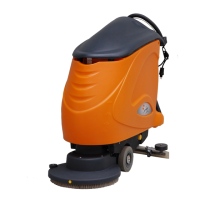
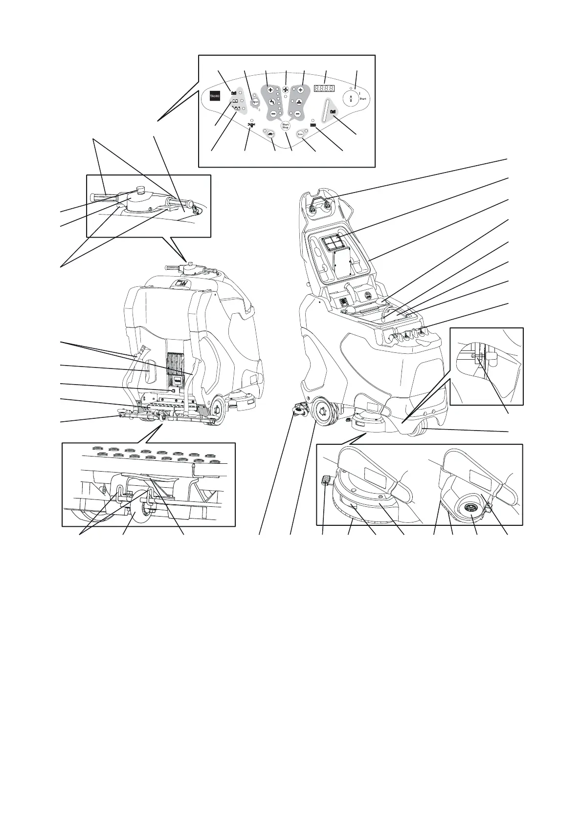
Structural layout
1 in the control panel
2 Driving handles
3 Emergency stop
4 Horn
5 Driving switch
6 Suction hose
7 Main cord for internal battery charger
8 Electronic parking brake
9 Tread with safety switch
10 Squeegee
11 Squeegee position lock
12 Squeegee support wheel
13 Squeegee holder
14 Squeegee deflecting roller
15 Drive wheel
16 Brush release XP-R
17 Brush
18 Brush unit deflecting roller XP-R
19 Brush unit XP-R
20 Brush release XP-M
21 Micro rotary brush
22 Brush unit deflecting roller XP-M
23 Brush unit XP-M
24 Swivel caster
25 Battery compartment release
26 Drain hose
27 Fresh water tank (Flextank)
28 Recovery tank
29 Pump and intake filter
30 Dirt sieve
31 Tank lid
32 Suction filter
33 Tank lid release
34 Battery display loading
35 Battery/PSU fault display
36 Service display
37 Slow approach button (ON/OFF)
38 Program button (start / stop)
39 ECO mode button (ON/OFF)
40 Recovery tank full display
41 Battery level indicator
42 Key switch
43 Display
44 Brush drive button (ON/OFF), brush pressure button (+/-)
45 Suction unit button (ON/OFF)
46 Cleaning solution supply button (ON/OFF), volume button (+/-)
47 Spot mode button (ON/OFF)
48 Battery display loaded
3
4
6
7
8
9
10
11 12 14 15 1716 20 21 22 23
24
26
27
28
29
30
31
32
25
18 1913
5
1
33
2
XP-R XP-M
35
34
36 37 38 39 40
424344464748 45
41